(No.MB066)1-11
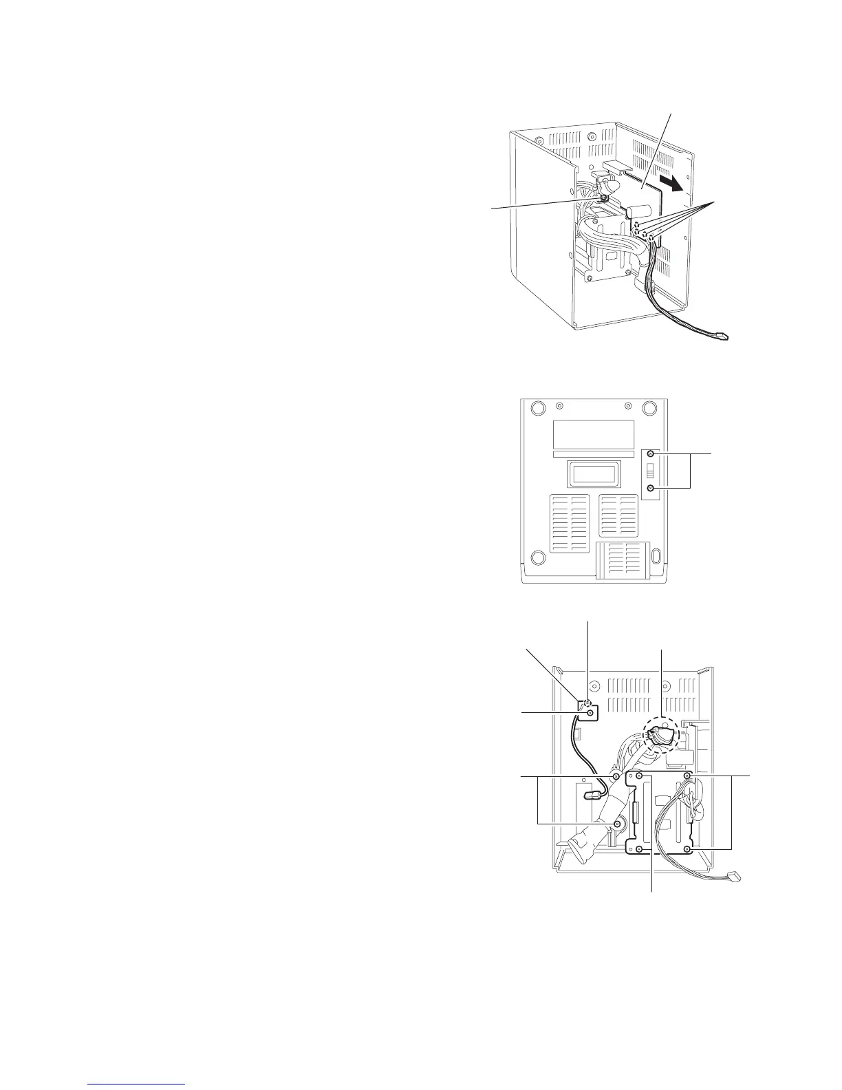
3.1.8 Removing the Transformer board
(See Fig.17)
• Prior to performing the following procedure, remove the front
panel assembly.
(1) Remove the screw Q on the rear cover assembly.
(2) Pull out the transformer board in the direction of the arrow.
(3) Unsolder the wire extending from the transformer.
Fig.17
3.1.9 Removing the Transformer
(See Fig.18 , 19)
• Prior to performing the following procedure, remove the front
panel assembly and the transformer board.
(1) Remove the two screws R attaching the voltage selector on
the bottom of the rear cover assembly.
(2) Remove the four screws S on the rear cover assembly.
(3) Remove the two screws T setting the power cord on the
rear cover assembly.
(4) Cut off the band connecting the power cord to the
transformer if necessary, remove the transformer.
3.1.10 Removing the FM-antenna board
(See Fig.19)
• Prior to performing the following procedure, remove the front
panel assembly.
(1) Remove the screw U on the rear cover assembly.
(2) Unsolder the FM-antenna wire on the FM-antenna board.
Fig.18
Fig.19
Q
Trans borad
Solder point
R
U
T
S
S
FM ANT board
Solder point
e Section
 Loading...