1-9
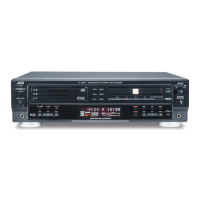
XL-R5000BK
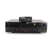
Disconnect the relay board.
Remove the five screws N and the operation switch
board from the front panel.
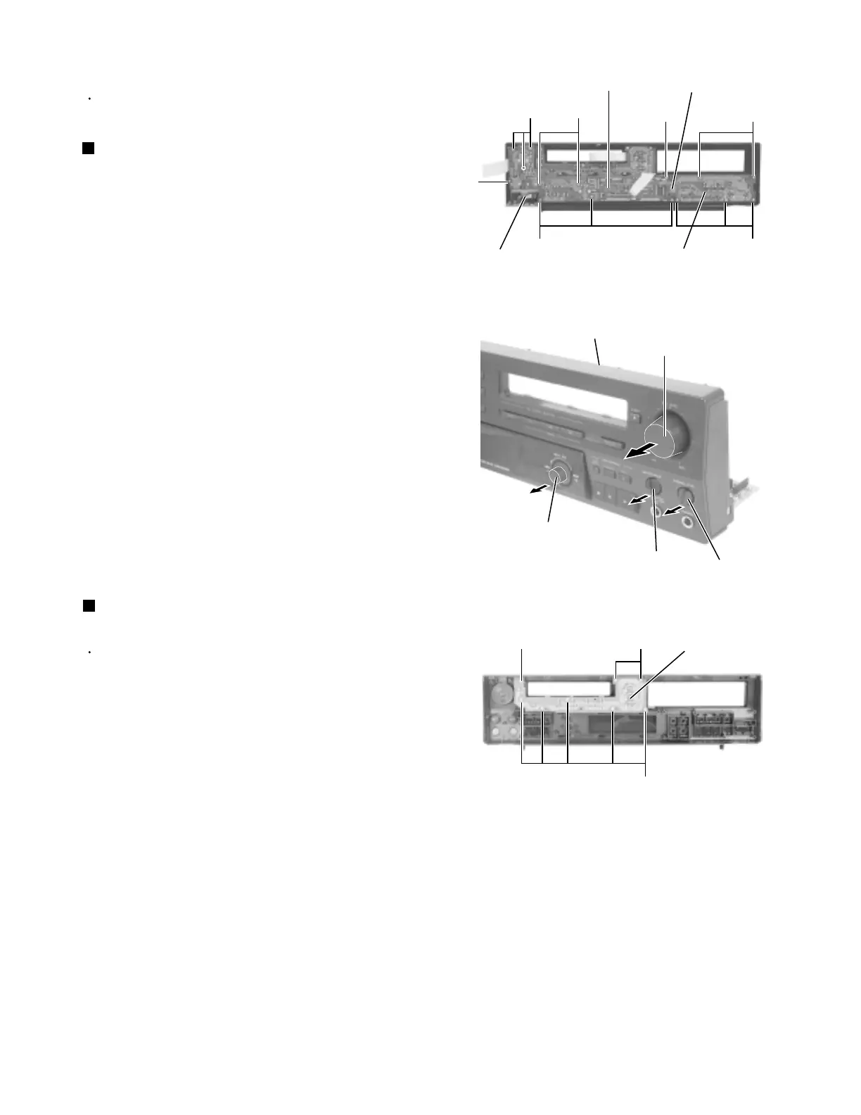
Pull out the two control knobs, the REC LEVEL knob
and the MULTI JOG knob respectively.
Remove the ten screws O and the display board
from the front panel.
1.
2.
3.
4.
<Front panel assembly>
Removing the operation switch board /
the display board (See Fig.19 and 20)
Prior to performing the following procedure, remove
the relay board and the display board.
Remove the eight screws P and the operation
switch board from the front panel.
1.
Removing the operation switch board
(See Fig.21)
Prior to performing the following procedure, remove
the top cover and the front panel assembly.
Fig.19
Fig.20
Fig.21
Display board
Front panel
assembly
Operation switch board
O
ON
OO O N
Relay board
REC LEVEL knob
Front panel assembly
MULTI JOG knob
Control knob
Operation switch board
P
PP
Control knob
www.freeservicemanuals.info
Digitized in Heiloo the Netherlands
 Loading...