XV-SA600BK/XV-SA602SL
36
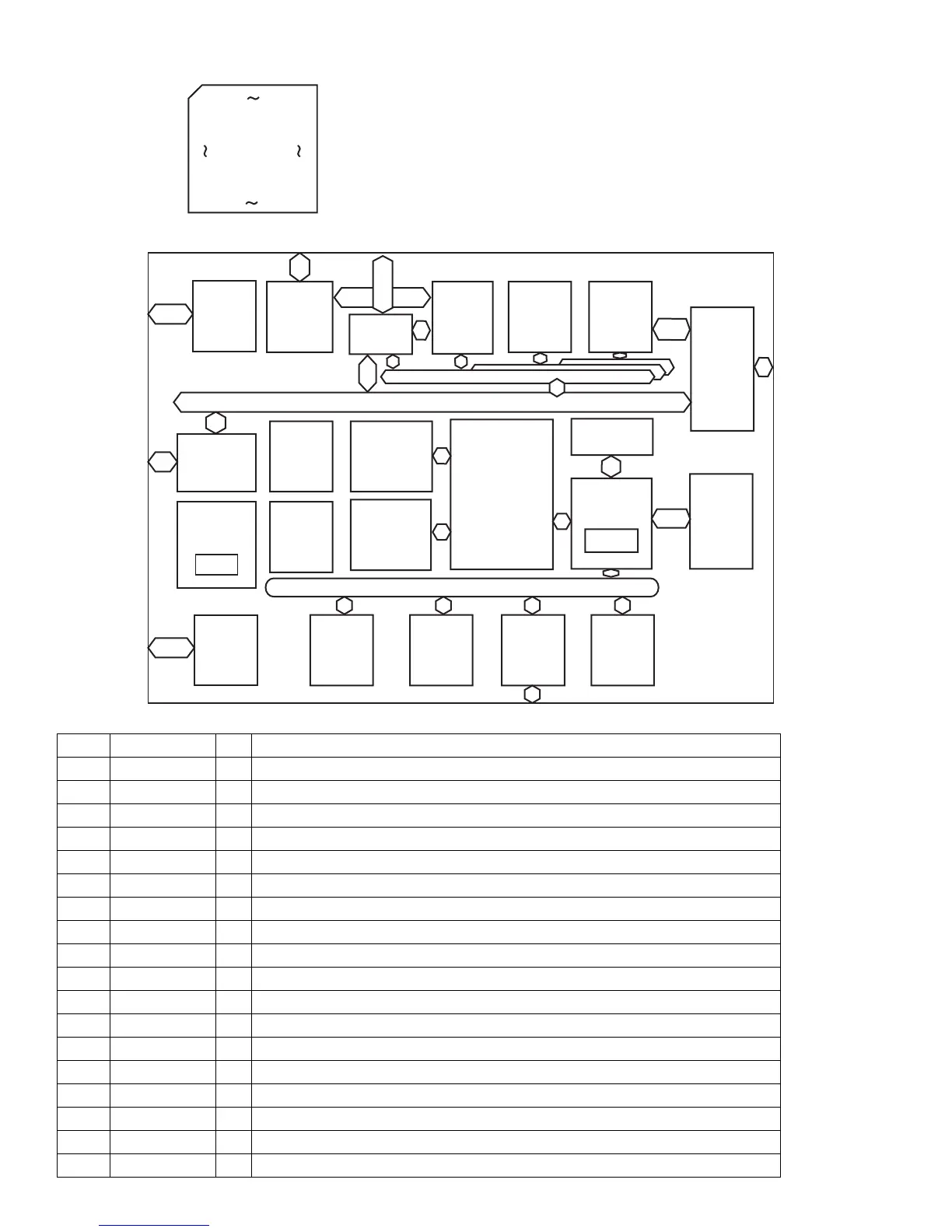
4.10 MN103S26EGA (IC301) : Super optical disc controller
4.10.1 Terminal layout
4.10.2 Block diagram
4.10.3 Pin function (1/4)
1
44
13
89
176 133
45 88
DVD-ROM
Formatter
CGEN
CD-PRE
Instruction
memory
(40KB)
DMA
I/F
ECC
Host I/F
MPEG I/F
High speed IO bus
32 bit
CPU core
DMA
Data
memory
(6KB)
BCU
DRAMC
ATAPI
2Mbit
DRAM
INTC
SYSTEM
I/F
16 bit
timer x 2
WDT
CIRC
General purpose IO bus
MODE
Servo I/O
(core 1 I/O)
Analog
Servo core
(core 2)
RAM
Pin No. Symbol I/O Description
1,2 NINT0,1 O Interruption of system control 0,1
3 VDD3 - Power supply terminal for I/O(3.3V)
4 VSS - Connect to ground
5 NINT2 O Interruption of system control 2
6 WAITDOC O Wait control of system control
7 NMPST O Reset of system control (Non connect)
8 DASPST I Setting of initial value of DASP signal
9~17 CPUADR17~9 I System control address
18 VDD18 - Power supply terminal for I/O (1.8V)
19 VSS - Connect to ground
20 DRAMVDD18 - Power supply terminal for DRAM (1.8V)
21 DRAMVSS - Connect to ground for DRAM
22~30 CPUADR8~0 I System control address
31 VDD3 - Power supply terminal for I/O (3.3V)
32 VSS - Connect to ground
33 DRAMVDD3 - Power supply terminal for DRAM (3.3V)
34 NCS I System control chip select
35 NWR I Writing system control
 Loading...