XV-SA600BK/XV-SA602SL
13
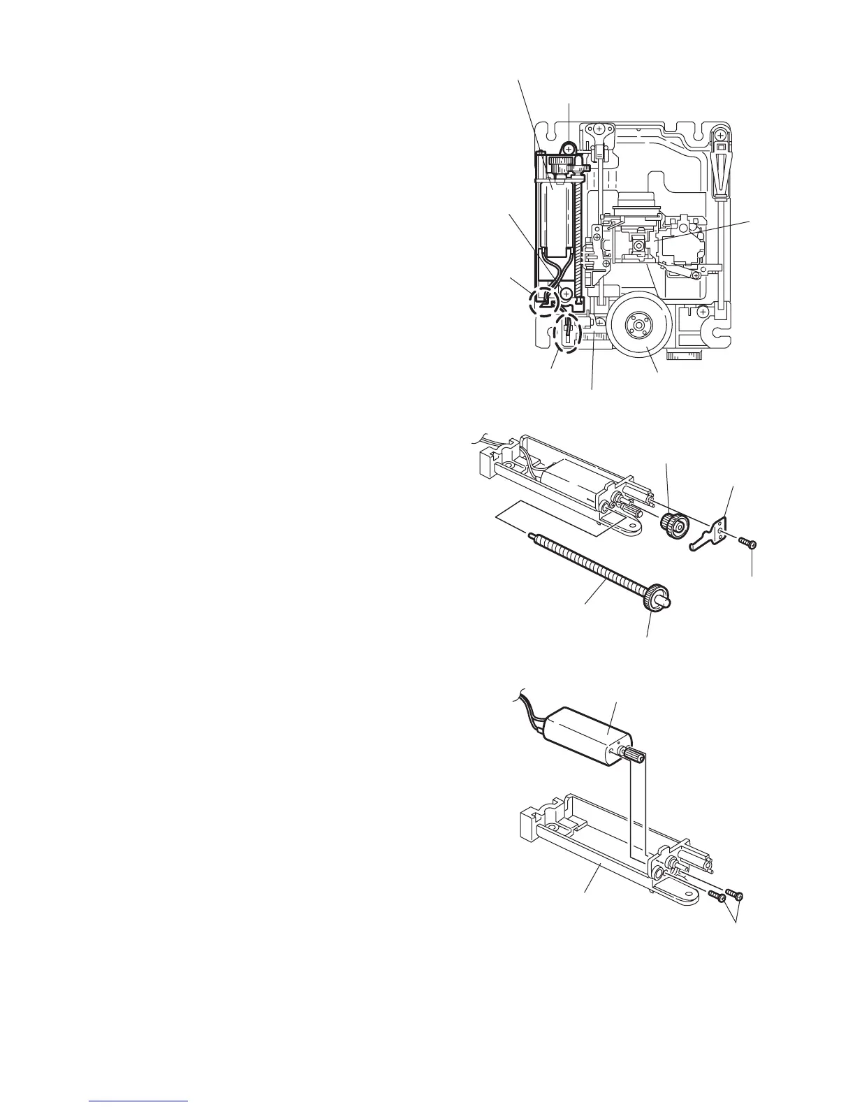
2.3 Traverse mechanism assembly section
2.3.1 Removing the feed motor assembly
(See Fig.2-19)
(1) Unsolder the two soldering j on the spindle motor
board.
(2) Remove the four screws F attaching the feed
motor assembly.
2.3.2 Removing the feed motor
(See Fig.2-19 to 2-21)
• Prior to performing the following procedure, remove
the feed motor assembly.
(1) Remove the screw G attaching the thrust spring.
ATTENTION:
When reattaching the thrust spring, make sure
that the thrust spring presses the feed gear (M)
and the feed gear (E) reasonably.
(2) Remove the feed gear (M).
(3) Pull out the feed gear (E) and the lead screw.
(4) Remove the two screws H attaching the feed motor.
ATTENTION:
When reattaching, pass the two cables extending
from the feed motor through the notch k of the
feed holder as shown in Fig2-20.
Fig.2-19
Fig.2-20
Fig.2-21
F
Soldering j
Notch k
F
Feed motor assembly
Spindle motor board
Spindle motor
Picku
Feed gear (M)
Thrust sprin
G
Lead screw
Feed motor
Feed holder
 Loading...