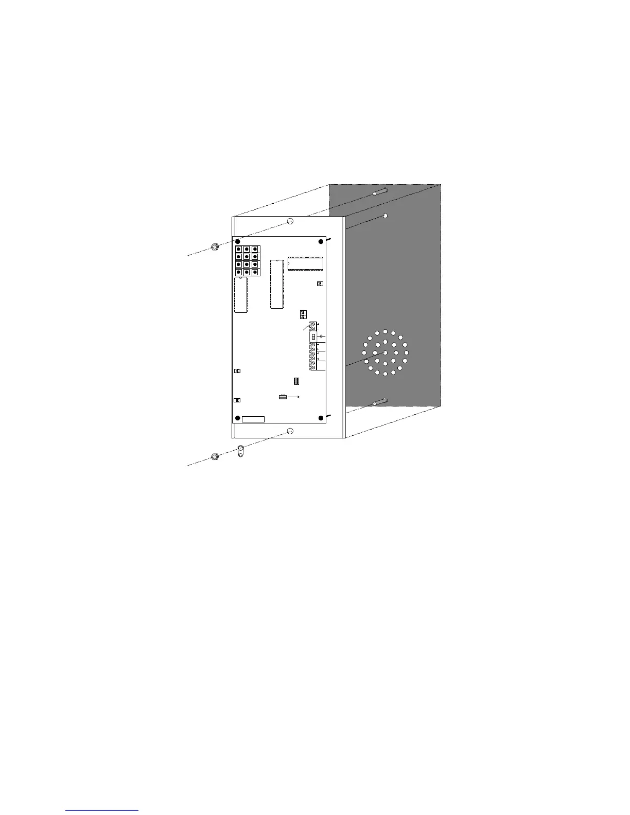
Using the faceplate as a template, align the microphone and
speaker with the grill pattern; mark and install the mounting
studs.
Mount the faceplate tightly against the back of the COP to avoid
feedback between the microphone and speaker.
MICROPHONE
SPEAKER
Increase
VOL.
9
6
3
#*
1
4
7
2
5
8
0
BUT
LED
+
-
9.0 VDC IN
REMOTE
LED
2V 7mA
PHONE
LINE
R
T
REMOTE
BUTTON
Dry
Contacts
9 - 24V
ONLINE
PROG
AUX
POWER
RINGS
5 -
7 -
9 -
K-Tech International Inc.
Part # PCB009 Rev D.
SERIAL #
Connect the normally open (NO) contacts of the push-button to
the terminal labeled REMOTE BUTTON (see Wiring Diagram on
page 6).
Connect the visual indicator to the terminals labeled REMOTE
LED taking care to follow the correct polarity.
Proceed to Settings on page 11.
Proceed to Programming on page 12.