10
Ajuste de la cerradura
1
3
⁄8 pulg. (35 mm) a 1
1
⁄2 pulg. (38 mm)
Adjusting the lock
1
3
⁄8" (35 mm) to 1
1
⁄2" (38 mm)
4a
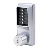
The 1000 Series lockset has been
preassembled at the factory to
accommodate doors 1
5
⁄8" (41 mm) to 1
7
⁄8"
(48 mm) thick.
For doors 1
3
⁄8" (35 mm) to 1
1
⁄2" (38 mm)
thick, adjust lock as follows: (see figure
4-1)
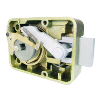
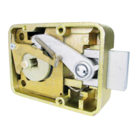
1. Remove the back plate assembly (AA) by
removing the six back plate screws. One
of the screws may be under the serial
number sticker.
2. Remove the cylindrical drive unit (CC)
from the back plate assembly (AA) by
removing the four Phillips head sems
screws (EE) from the underside of the
back plate (AA).
3. Remove (and discard) the spacer (BB)
located between the back plate
assembly (AA) and the cylindrical drive
unit (CC).
4. Remount the cylindrical drive unit (CC)
onto the back plate assembly (AA) using
the four 8-32 x
3
⁄
16
(5 mm) shorter Phillips
head sems screws provided (item “k”
from the checklist).
5. Remove the cross pin from position B on
the drive shaft (DD).
6. Reposition the cross pin in position C on
the drive shaft (DD).
7. Reinstall the back plate assembly (AA)
onto the front lock case.
La cerradura Serie 1000 ha sido ensamblada
en fábrica para las puertas de 1
5
⁄
8 pulg.
(41 mm) a 1
7
⁄8 pulg. (48 mm) de espesor.
Para las puertas de 1
3
⁄
8 pulg. (35 mm) a
1
1
⁄2 pulg. (38 mm) de espesor, ajuste la
cerradura de la manera siguiente (véase
la ilustración 4-1):
1. Quite la placa de montaje posterior (AA),
sacando los seis tornillos que están en esa
placa. Uno de los tornillos puede ir debajo
de la etiqueta con el número de serie.
2. Saque la unidad cilíndrica (CC) de esa
placa (AA), quitando los cuatro tornillos
Phillips (EE) de la parte de adentro de la
placa (AA).
3. Quite (y descarte) el espaciador (BB)
situado entre la placa posterior (AA) y la
unidad cilíndrica (CC).
4. Vuelva a montar la unidad cilíndrica (CC)
sobre la placa posterior (AA), utilizando
los cuatro tornillos Phillips más cortos,
8-32 x
3
⁄16 (5 mm), provistos (artículo “k”
en la hoja de verificación).
5. Quite el pasador transversal de la posición
B del eje (DD).
6. Vuelva a instalar el pasador transversal en
la posición C del eje.
7. Vuelva a instalar la placa de montaje
posterior (AA) en la caja delantera de la
cerradura.

 Loading...