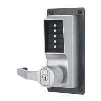
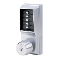
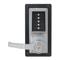
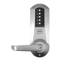
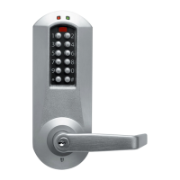
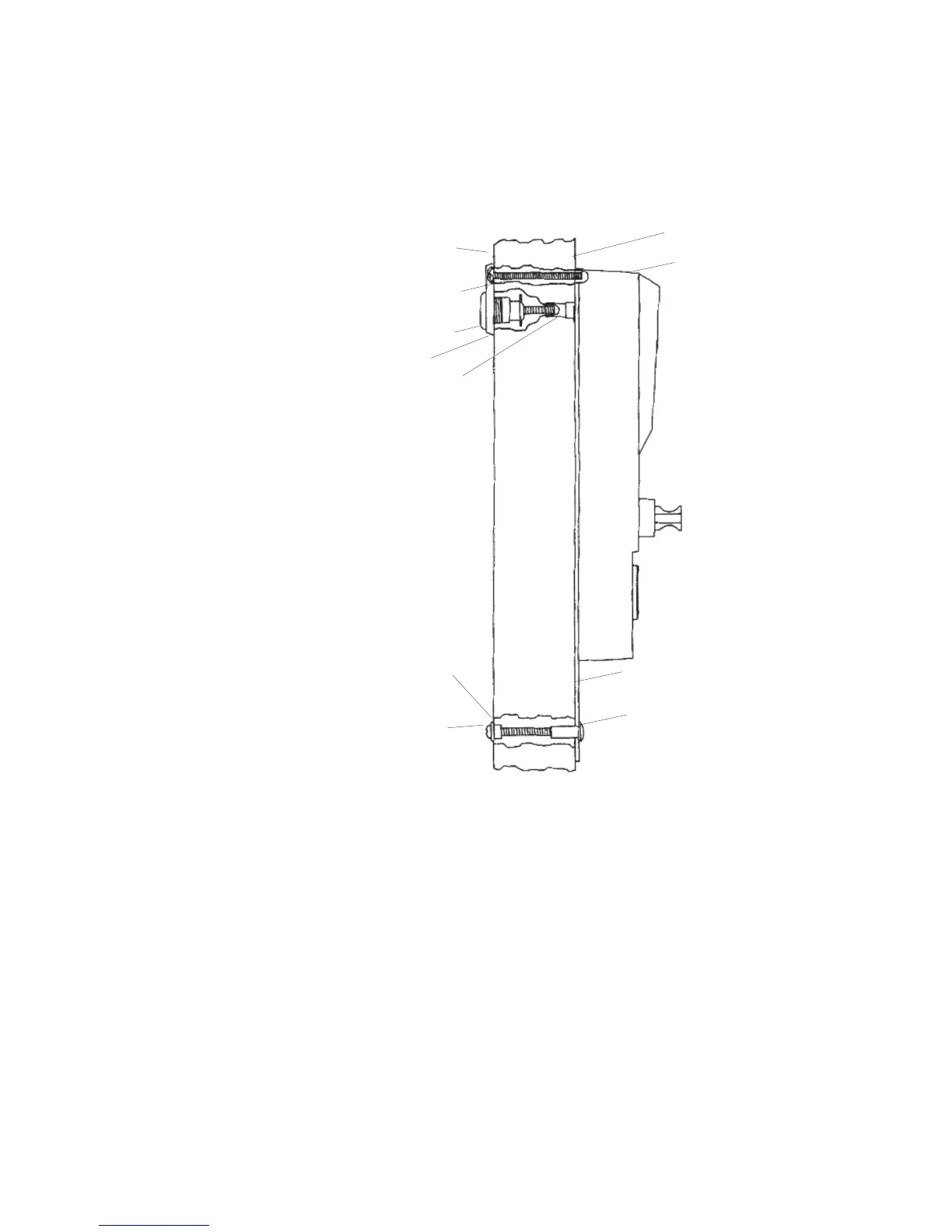
5
B-2 Fix two each 10-24 x 2
1
⁄8" long round head machine screws (A) as shown
(See Figures 2-1 & 2-2). Using the DF-59 key, thread the control lock
assembly (B) into the combination change sleeve (C) DF-59 (See Figure
2-2) until trim plate is snug against stile. The key can only be removed in
vertical position.
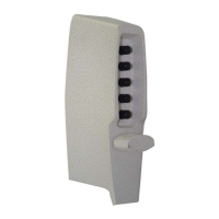
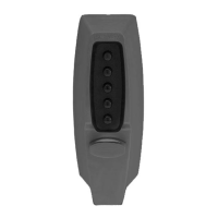
N
arrow Stile Combination
L
ock Side
Narrow Stile
T
rim Plate Side
C
ombination Lock
Assembly Side View
Drive Assembly
Threaded Sex Bolts
N
arrow Stile Door Edge View
B
Trim Plate
C
Mounting Bushing
Mounting Screws
A
Figure 2-2