Do you have a question about the Kaba Simplex 7104 Series and is the answer not in the manual?
Key warnings and important notes for safe and correct installation.
List of tools needed to perform the lock installation.
Verify all components are included before starting installation.
Identify door swing direction (inward/outward, left/right).
Position the exterior thumbturn at least 7 inches above the primary lock.
Modify the latch backset from 2 3/4" to 2 3/8" if needed.
Use the template to mark hole locations precisely on the door edge.
Drill specified holes (1/4", 13/8", 3/4", 1") accurately for the lockset.
Create a recess for the latch face plate to sit flush with the door edge.
Insert and secure the latch into the prepared door hole.
Attach the trim plate to the back of the lock housing.
Shorten tailpieces X and Y based on door thickness for proper fit.
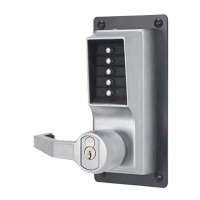
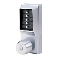
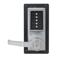
Attach exterior lock assembly and interior thumbturn assembly using thru-bolts.
Ensure tailpieces X and Y engage correctly with latch and combination assemblies.
Test outside and inside thumbturns for proper latch retraction and extension.
Readjust thumbturn assemblies if latch does not retract correctly.
Mark, drill, and mortise door frame for strike plate alignment.
Fasten the strike plate to the door frame with screws.
Remove the back plate and dust cover to access the combination mechanism.
Align code gear pockets to shear line and set new combination using key-stems.
Replace dust cover, combination chamber, and back plate after setting new combination.
Address issues with button depression, clearing entries, or zero combination.
Troubleshoot partial latch retraction or failure to retract with thumbturns.
Resolve issues where the lock works only once after changing the combination.
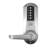
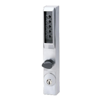
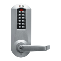
| Type | Mechanical Pushbutton Lock |
|---|---|
| Mounting | Surface Mount |
| Dimensions | Varies by model |
| Backset | 2-3/4" (70 mm) |
| Handing | Non-Handed |
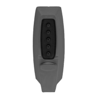
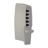
| Buttons | 5 |
| Operation | Pushbutton Combination Entry |
| Combinations | Thousands of possible combinations |