8
I. INSTALLING THE LOCK
- For 1
3
⁄4" - 1
3
⁄4" (33 - 44 mm) thick doors, use the 2
3
⁄8" (45 mm) thru bolts.
- For 2"- 2
1
⁄4" (51- 57 mm) thick doors, use the 3" (76 mm) thru bolts.
Mount the lock from the outside of the door.
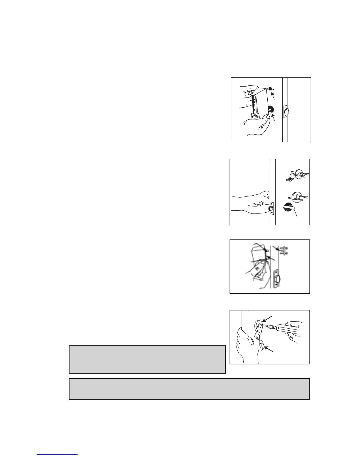
I-1 Insert the tailpiece Y into the horizontal cutout
of the latch assembly and the tail piece X into
the
3
⁄8" (19 mm) hole (See Figure 9-1).
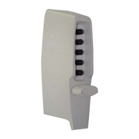
I-2 Hold the exterior lock assembly (pg.7, A) firmly
against the door. Try the factory-set combina-
tion. Press buttons #2 and #4 together,
release, press button #3, and release. A dis-
tinctive click must be felt to indicate that the
button has been correctly depressed. Turn the
outside thumbturn to the right (clockwise) to
the stop position (the lach should be fully
retracted). If not, turn the thumbturn to the
left (counter clockwise) to the stop position
and repeat Step 2.
I-3 While holding the lock firmly against the out-
side surface of the door with one hand, use
the other to mount the inside thumbturn
assembly (pg.7, D) to the interior side of the
door with two thru-bolts finger tight (See
Figure 9-2). Make sure that tailpiece Y is
engaged into the horizontal cutout of the
inside thumbturn assembly.
I-4 Insert tailpiece X into the horizontal slot of
the combination change assembly, (pg.7, E). It
may be necessary to use a screwdriver to align
tailpiece X with the combination change
assembly (See Figure 9-2 and 9-3). Once
aligned, secure with two thru-bolts, but do not
tighten, (See Figure 9-4).
Note: The inside thumbturn is shown in a vertical
position to show the two thrubolts. It may be
assembled either vertically or horizontally.
IMPORTANT: Tailpiece X must be inserted in the horizontal slot in order to
change your combination.
I-5 Make sure that assemblies A and B are correctly centered over the holes
(See Figure 9-4). Tighten the thru-bolts evenly. Uneven tension could
cause a malfunction of the lock.
9-4
9-3
9-1
9-2
X
Y
Y
X
Y