5
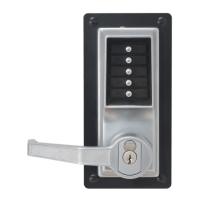
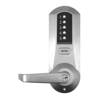
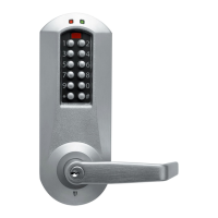
A. DETERMINING THE LOCK LOCATION
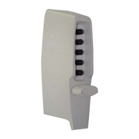
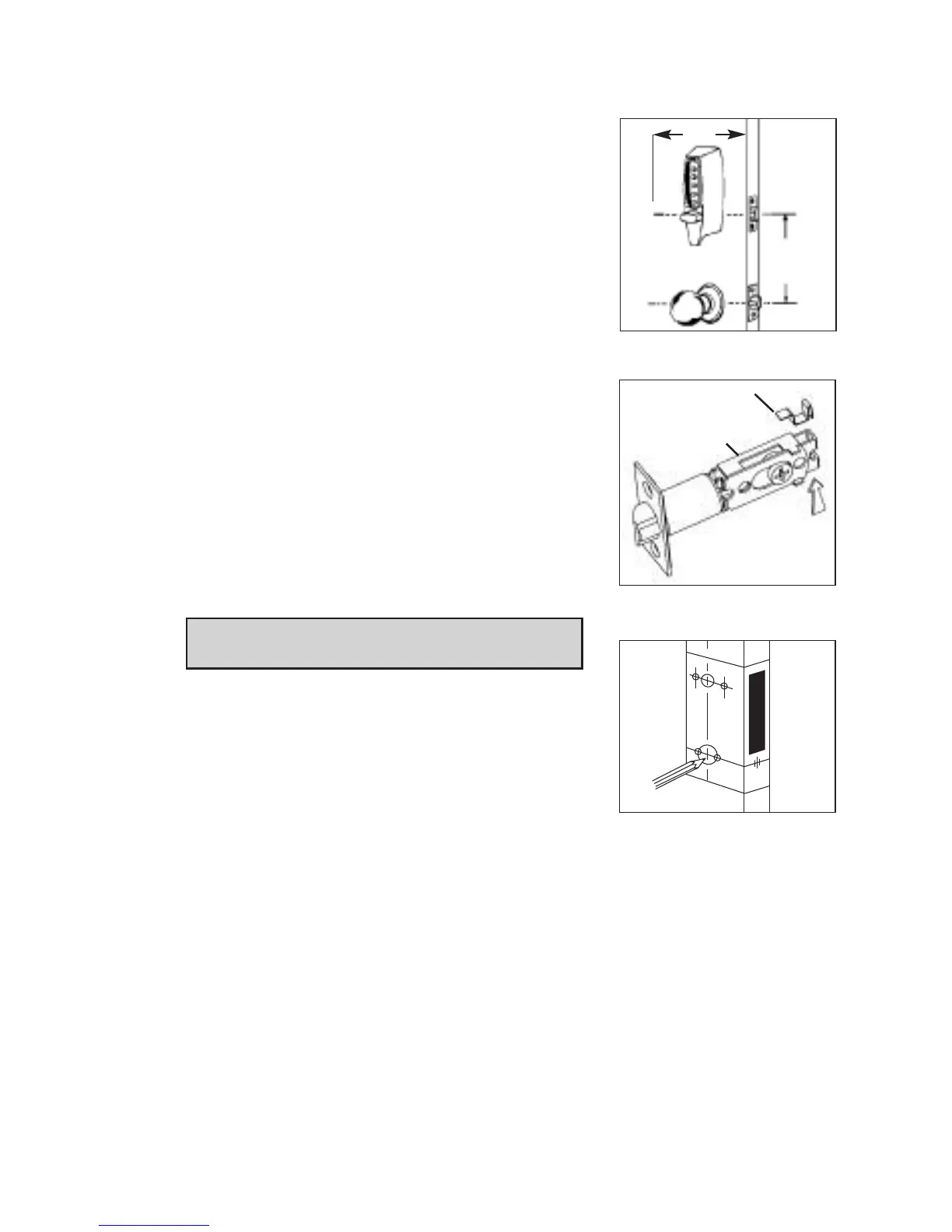
Install the lock with the exterior thumbturn at least
7" (18 cm) above your primary lock set so it is com-
fortable to operate and not in the way when you
turn the door knob. *A minimum stile width of
4" (10.16 cm) is required for mounting,
(See Figure 2-1).
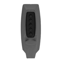
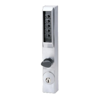
B. ADJUSTING THE LATCH
(Model 7014 only)
This latch has been secured in the 2
3
⁄4" back set
position with a spring clip. If your application
requires a 2
3
⁄8" back set, remove the spring clip
by utilizing a small screw driver (or similar) and
inserting the tip through the latch as indicated by
the arrow, and gently pressing on the spring clip
until is removed from the latch.
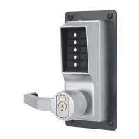
C. MARKING THE DOOR
NOTE: Be sure to use the correct template
(right-hand or left-hand door - 2
3
⁄8" or 2
3
⁄4").
C-1 Carefully fold the template (found in the center
of this booklet) as indicated (See Figure 3-1).
C-2 Tape the template securely to the outside of
the door so that all the indicated folds are
properly aligned with the edge of the door.
C-3 Use a center punch to make the marks for
drilling the seven holes precisely at the points
indicated on the template. The cen-ter punch mark in the edge of the
door must be centered based on the thickness of the door.
C-4 Remove the template.
1-1
7"
(
18 cm)
*4"
2-1
Spring Clip
Adjustable Latch
3-1