English–2
Bosch eBike Systems 0 276 001 SPI | (22.8.13)
Indication Elements, HMI
a Motor-output indicator
b Assistance-level indicator
c Illumination indicator
d Text indication
e Value indication
f Speed indication
g Battery charge-control indicator
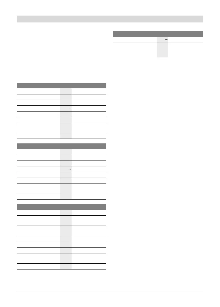
Technical Data
Assembly
Inserting and Removing the Battery Pack
For inserting and removing the battery pack in/from the
eBike, please read and observe the battery pack operating in-
structions.
Inserting and Removing the HMI (see figure A)
To insert the HMI 3, slide it from the front into the holder 4.
To remove the HMI 3, press the lock latch 15 and slide the
HMI toward the front out of the holder 4.
Remove the HMI when you park the eBike.
It is possible to secure the HMI against removal in the holder.
To do so, remove the holder 4 from the handlebars. Put the
HMI in the holder. Screw the locking screw 16 (thread M3,
8 mm long) from below into the thread provided in the holder.
Mount the holder back onto the handlebars.
Checking the Speed Sensor (see figure B)
The speed sensor 17 and its spoke magnet 18 must be
mounted in such a manner that the spoke magnet, after a turn
of the wheel, moves past the speed sensor with a clearance of
at least 5 mm, yet no more than 17 mm.
Note: If the clearance between speed sensor 17 and spoke
magnet 18 is too small or too large, or if the speed sensor 17
is not properly connected, the speed indication f will fail, and
the eBike drive will operate in emergency mode.
In this case, loosen the screw of the spoke magnet 18 and fas-
ten the spoke magnet to the spoke in such a manner that it
runs past the mark of the speed sensor at the correct clear-
ance. When the speed is still not being indicated in the speed
indication f after this, please refer to an authorised bicycle
dealer.
Drive Unit Drive Unit Cruise
Article number
0 275 007 023
Rated continuous output
W250
Torque at drive, max.
Nm 60
Rated voltage
V36
Operating temperature
°C –5...+40
Storage temperature
°C –10...+50
Degree of protection
IP 54 (dust and splash
water protected)
Weight, approx.
kg 4
Drive Unit Drive Unit Speed
Article number
0 275 007 021
Rated continuous output
W350
Torque at drive, max.
Nm 60
Rated voltage
V36
Operating temperature
°C –5...+40
Storage temperature
°C –10...+50
Degree of protection
IP 54 (dust and splash
water protected)
Weight, approx.
kg 4
HMI Intuvia
Article number
1 270 020 909
Max. charging current,
USB connection
mA 500
Charging voltage,
USB connection
V5
Operating temperature
°C –5...+40
Storage temperature
°C –10...+50
Charging temperature
°C 0...+40
Degree of protection
IP 54 (dust and splash
water protected)
Weight, approx.
kg 0.15
Lighting*
Rated voltage V6
Power output
–Front light
–Rear light
W
W
6.6
0.6
* Not possible via the eBike battery pack in all country-specific versions,
depending on the statutory regulations
OBJ_BUCH-2087-001.book Page 2 Thursday, August 22, 2013 11:11 AM
 Loading...