EasyManua.ls Logo

Kamstrup ULTRAFLOW 54 DN15-125 - User Manual

Kamstrup ULTRAFLOW 54 DN15-125
90 pages
Print Icon
To Next Page IconTo Next Page
Loading...
Kamstrup A/S · Industrivej 28, Stilling · DK-8660 Skanderborg · T: +45 89 93 10 00 · info@kamstrup.com · kamstrup.com
Technical description
ULTRAFLOW® 54
DN15-125

Table of Contents

Questions and Answers

  • M
    Misty HarveyAug 13, 2025
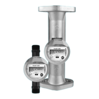
    What to do if my Kamstrup ULTRAFLOW 54 DN15-125 Measuring Instruments do not accumulate m³?
    • S
      Shannon MillerAug 13, 2025
      If the Kamstrup Measuring Instruments do not accumulate m³, first, check the flow sensor connection, using a pulse tester if necessary. Also, verify the flow sensor direction and inspect the system for air or cavitation from valves and pumps. If possible, increase the static pressure. As a last resort, replace the flow sensor or send the meter for repair.
  • J
    Jennifer BrewerAug 16, 2025
    Why are the display values not updating on my Kamstrup ULTRAFLOW 54 DN15-125?
    • C
      Cynthia HillAug 17, 2025
      If your Kamstrup Measuring Instruments display values are not updating, it might be due to no power supply. Try replacing the battery or checking the mains supply.
  • G
    gmaloneAug 20, 2025
    What to do if my Kamstrup ULTRAFLOW 54 DN15-125 Measuring Instruments accumulate m³ erroneously?
    • B
      bradshawjosephAug 20, 2025
      If the Kamstrup Measuring Instruments erroneously accumulate m³, ensure the meter factors of the calculator and flow sensor correspond to prevent erroneous programming. Also, check the system for air or cavitation from valves and pumps. If possible, increase the static pressure. If the issue persists, replace the flow sensor or send the sensor for repair.
  • E
    Emma ScottAug 25, 2025
    How to fix a blank display on Kamstrup ULTRAFLOW 54 DN15-125?
    • B
      Bradley PhillipsAug 25, 2025
      If your Kamstrup Measuring Instruments display is blank, it could be due to no power supply and backup. Replace the back-up cell and replace the battery or check the mains supply.
  • L
    ldavisAug 27, 2025
    What to do if Kamstrup ULTRAFLOW 54 DN15-125 Measuring Instruments do not accumulate m³?
    • C
      Casey PetersAug 27, 2025
      If the Kamstrup Measuring Instruments do not accumulate m³, first, check the flow sensor connection, using a PULSE TESTER if needed. Then, ensure the connection is correct and the flow sensor isn't inverted. Also, verify that there's no air in the sensor or cavitation from valves and pumps. Finally, if all else fails, the flow sensor might be faulty and require replacement or the meter needs repair.
  • K
    Kevin PorterAug 31, 2025
    How to fix Kamstrup ULTRAFLOW 54 DN15-125 when display values are not updating?
    • J
      Jennifer EatonAug 31, 2025
      If the display values on your Kamstrup Measuring Instruments aren't updating, the most common cause is a lack of power. Try replacing the battery or checking the mains supply to resolve this.
  • C
    Christine RobinsonSep 4, 2025
    Why are Kamstrup ULTRAFLOW 54 DN15-125 Measuring Instruments erroneously accumulating m³?
    • G
      Gina MccormickSep 4, 2025
      If the Kamstrup Measuring Instruments are erroneously accumulating m³, you should first check that the meter factors of the calculator and flow sensor correspond, as erroneous programming might be the cause. Also, check if there is air in the system or cavitation from valves and pumps. If the issue persists, the flow sensor may be faulty and require replacement or repair.
  • A
    Alicia HansonSep 8, 2025
    What to do if Kamstrup ULTRAFLOW 54 DN15-125 Measuring Instruments display is blank?
    • T
      Travis SmithSep 8, 2025
      If your Kamstrup Measuring Instruments have a blank display, it indicates a lack of power supply and backup. To solve this, replace the back-up cell and replace the battery or check the mains supply.

Summary

Technical Description

Introduction to ULTRAFLOW 54

Pioneering Work and Continuous Development

Kamstrup's history and advancements in ultrasonic flow sensor technology.

Modular Meter Set-up for Maximum Flexibility

Describes the flexible installation options with separate flow sensors and calculators.

General Description of ULTRAFLOW 54

Overview of the ULTRAFLOW 54 sensor, its technology, and connectivity.

Technical Data for ULTRAFLOW 54

Approved Meter Data

Details on MID designation, environments, and accuracy class.

Electrical Data

Specifications for supply voltage, battery lifetime, and cable lengths.

Mechanical Data

Information on accuracy class, environments, protection, and pressure stages.

Flow Data

Table detailing nominal flow, meter factor, dynamic range, and cutoff.

Materials

Lists materials used for wetted parts and electronic housings.

Type Overview

Ordering Details and Accessories

Type Numbers of ULTRAFLOW 54

Table listing various ULTRAFLOW 54 type numbers with specifications.

Accessories for ULTRAFLOW 54

Details on couplings, gaskets, and other accessories.

Pulse Transmitter; Pulse Divider and Cable Extender Box

Introduction to accessories for extending functionality and cable length.

Dimension Sketches

Threaded Meters

Dimension drawings and weights for threaded ULTRAFLOW 54 models.

Flange Meters

Dimension drawings and weights for flanged ULTRAFLOW 54 models.

Installation Guidelines

Guidelines for Dimensioning and Operating Conditions

Recommendations for proper installation and operating environment.

Connections, Accessories and Assembly

Details on electrical connections, couplings, and sensor mounting.

Cable Length of ULTRAFLOW 54

Information on standard and extended cable lengths for the flow sensor.

Flow Sensor Position (Inlet;Outlet)

Guidance on correct orientation of the flow sensor for measurement.

Insulation Recommendations

Overview of insulation recommendations for flow and temperature sensors.

Inlet Prerequisites

General installation recommendations for flow sensors to ensure accurate measurement.

Orientation of Kamstrups Flow Sensors

Recommendations for sensor orientation for optimal performance.

Mounting of Pulse Transmitter and Pulse Divider

Guidance on proper mounting orientation and wall-mounting.

Mounting of Cable Extender Box

Instructions for mounting the Cable Extender Box.

Installation Examples (Mechanical)

Examples of mounting calculators like MULTICAL 603 and 803 on the flow sensor.

Insulation of ULTRAFLOW 54 (DN15-125)

Specific instructions regarding insulation of the flow sensor's plastic casing.

Electrical Connections

Electrical Connection of ULTRAFLOW and MULTICAL

Wiring diagram for connecting ULTRAFLOW to MULTICAL calculators.

Electrical Connection of Pulse Transmitter and Pulse Divider

Wiring for connecting ULTRAFLOW via Pulse Transmitter/Pulse Divider.

Connection of Power Supply

Details on battery and mains supply modules for Pulse Transmitter/Divider.

Electrical Connection of Cable Extender Box

Wiring instructions for connecting the Cable Extender Box.

Installation Examples (Electrical)

Examples of electrical connections for ULTRAFLOW and accessories.

Functional Description

Flow Measurement with Ultrasound

Explanation of the ultrasonic measurement principles used.

Signal Path, Flow Calculation and Flow Profiles

How signals are processed to calculate flow velocity and volume.

Function of ULTRAFLOW

Description of the sensor's operational sequences and pulse emission.

Pulse Emission

Details on pulse generation, duration, and signal characteristics.

Supply of ULTRAFLOW

Information on power supply options for the ULTRAFLOW sensor.

Pulse Output of ULTRAFLOW

Specifications for the sensor's pulse output signal.

Pulse Output of Pulse Transmitter and Pulse Divider

Details on galvanically separated output modules (Y=2 and Y=3).

Interface Connector;Serial Data

Description of the interface connector and its functions.

Test Mode

Instructions for switching the sensor into test mode for calibration.

Externally Controlled Start;Stop

How to control start/stop of measurements using external signals.

Calibration using Serial Data and Externally Controlled Start;Stop

Procedure for calibrating ULTRAFLOW using serial data and external control.

Accuracy

Details on measurement accuracy and tolerances according to EN 1434.

Calibration, Adjustment, and Sealing

Calibration Methods for ULTRAFLOW

Overview of calibration approaches: standard, test mode, and Pulse Tester.

Technical Data for ULTRAFLOW

Output signal specifications, including type, impedance, and pulse duration.

Electrical Connection

Details on wiring for direct connection and via Pulse Transmitter.

Suggested Test Points

Recommended test points, durations, and quantities for calibration.

Optimization in Connection with Calibration

Factors affecting calibration: pressure, temperature, water quality, and installation.

Pulse Tester Functions

Description of Pulse Tester functions: hold, push-buttons, and usage.

Sealing and Marking

Information on factory seals, laboratory markings, and re-verification marks.

Software for Kamstrup Heat;Cooling Meters

Approvals and Declarations

MID Approval

Details on MID heat meter approval and EU-type examination certificates.

CE Marking

Information on CE marking according to relevant EU directives.

EU Declaration of Conformity

Availability of the EU declaration of conformity document.

Troubleshooting

Disposal Information

Technical Documentation

Kamstrup ULTRAFLOW 54 DN15-125 Specifications

General IconGeneral
TypeUltrasonic flow sensor
Nominal diameterDN15-125
Measurement PrincipleUltrasonic transit time
Pressure RatingPN16
Protection ClassIP68
Temperature Range0°C
OutputsPulse, M-Bus, Modbus
Power Supply24 VAC/DC

Related product manuals