EasyManua.ls Logo

Kamstrup flowIQ 3100 User Manual

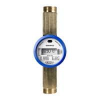
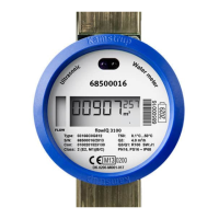
Kamstrup flowIQ 3100
60 pages
To Next Page IconTo Next Page
Page #1 background imageLoading...
Page #1 background image
Technical Description
flowI3100
Water Meter

Table of Contents

Other manuals for Kamstrup flowIQ 3100

Questions and Answers:

Kamstrup flowIQ 3100 Specifications

General IconGeneral
TypeUltrasonic water meter
ApplicationResidential and commercial water metering
Battery LifeUp to 16 years
Pressure ratingPN16
Protection ClassIP68
SizesDN15, DN20, DN25, DN40
Measuring range0.015 m³/h to 6 m³/h
CommunicationWireless M-Bus, Wired M-Bus
Power supplyBattery
Temperature range0.1°C to +50°C
ApprovalMID approved
Measurement principleUltrasonic
Flow rate range0.015 m³/h to 6 m³/h
Pipe diameter rangeDN15, DN20, DN25, DN40
MaterialBrass

Summary

General Description and Key Features

Product Overview

Describes the flowIQ® 3100 water meter and its core function.

Key Advantages

Highlights benefits like longevity, protection, and ultrasonic principle.

General Description - Front Plate and Sealing

Front Plate Information Details

Explains information labels and indicators on the meter's front plate.

Meter Sealing Mechanism

Describes the method used to seal the water meter.

Approvals and Technical Data - Mechanical

European Market Approvals

Details meter approval for European markets and relevant directives.

Mechanical Specifications

Covers ambient class, environment, accuracy, pressure stage, and protection.

Technical Data - Electrical and Materials

Electrical Specifications

Details battery, lifetime, and EMC data.

Material Composition

Lists materials used for wetted parts and meter housing.

Technical Data - Water Meter Types

Measurement Accuracy Standards

Temperature Measurement Specifications

Type Overview and Accessories

Type Configuration Overview

Describes meter configurations and communication options.

Accessory Information Reference

Refers to the accessories list document.

Configuration Settings and Data Logging

Dimensioned Sketches - Part 1

Dimensioned Sketches - Part 2

Dimensions - Connection Types

Threaded Connections (ISO 228-1)

Dimensions for threaded meter types.

Flanged Connections (DN)

Dimensions for flanged meter types.

Meter Size, Weight, and Connection Summary

Pressure Loss Specifications

Installation Requirements

Installation Conditions and Service

Installation Environment and Conditions

Sealing surface, gaskets, ambient temp, humidity, and pressure.

EMC Conditions and Service Restrictions

EMC marking and service limitations.

Installation Angle Flexibility

Describes permissible mounting angles for the meter.

Installation - Flow Conditions

Straight Inlet/Outlet Requirements

Specifies needs related to flow disturbances.

Operating Pressure Requirements

Details minimum static pressure needed.

Reading and Data Functions Overview

Meter Reading Methods

Visual, Wireless M-Bus, and optical eye reading methods.

Volume Measurement and Registers

How volume is calculated, saved, and stored.

Target Volume Data Function

Explanation of the target volume register.

Data Functions - Flow and Temperature Logging

Max/Min Flow Logging

Recording of maximum and minimum flow values.

Temperature Measurement and Logging

Details on water and ambient temperature data.

Data Functions - Temperature and Logging Options

Ambient/Meter Temperature Monitoring

Monitoring ambient and meter housing temperatures.

Water Temperature Monitoring

Monitoring of water temperature.

Optional Data Logging Selection

Options for data selection in the logger.

Optional Data Logging Configuration Diagram

Display Functions - Volume Display

Display Functions - Resolution and Indicators

Display Resolution Settings

How to adjust decimal places on the display.

Display Dots Functionality

Explains the meaning of flashing dots on the display.

Display Functions - Info Codes Overview

Display Functions - Info Codes (BURST, DRY, TAMPER)

BURST and DRY Info Codes

Explains burst detection and dry meter indication.

TAMPER Detection

Indicates unauthorized access or tampering.

Display Functions - Info Codes (REVERSE, RADIO OFF)

REVERSE Flow and RADIO OFF Mode

Explains reverse flow detection and transport mode.

Display Functions - Adjustment Mark

Display Functions - Flow Arrows

Wireless M-Bus Communication - Transmission

Wireless M-Bus Data Package Contents

Wired M-Bus Communication

Overview, Applications, and Standards

Covers introduction, applications, billing, and communication standards.

M-Bus Addressing

Details on primary, secondary, and enhanced secondary addressing.

Communication Speed, Intervals, and Configuration

Supported baud rates, intervals, and configuration methods.

Available Data Fields and Technical Specs

Lists data fields and technical specifications.

Optical Eye Interface for Data Access

Data Loggers and Memory Structure

Memory Structure

Details on permanent memory (EEPROM) and the types of registers available.

Data Loggers - Daily and Monthly Records

Monthly and Daily Logger Contents

Tables showing logged registers and data.

Hour Counter Functionality

How hour counters are incremented based on info codes.

Info Register Details

Info Code Logging Intervals and Conversion

Meter Operating Modes

Normal Mode Operation

Description of standard operating mode.

Verification Mode Operation

Description of meter verification mode.

Legal Changes Outside Seal

Legal Changes and Meter Reset Procedures

Flow Adjustment and Re-adjustment Procedures

Steps for flow curve adjustments.

Meter Reset Procedure for Re-verification

Steps for resetting the meter.

Measuring Principle - Ultrasound Technology

Ultrasound with Piezo Ceramics

Introduction to ultrasonic measurement technology.

Transit Time Measurement Method

Detailed explanation of the transit time measurement.

Measuring Principle - Flow Calculation Formulas

Measuring Principle - Flow Volume Calculation

Measuring Principle - Signal Path and Flow Limits

Signal Path Description

Describes the path of ultrasonic signals within the meter.

Flow Limits and Working Range

Explains minimum cut-off and maximum cut-off flow.

Pulse Adapter Functionality

Pulse Adapter - Installation and Environment

Application Environment and Lifetime

Environmental conditions and adapter lifespan.

Connecting the Pulse Adapter

Step-by-step procedure for installing the adapter.

Pulse Adapter - Setup and Pull-up Configuration

Setup Confirmation Display

Visual indication of successful adapter setup.

Pull-up Resistor Configuration

Explanation of pull-up for pulse output.

Pulse Adapter Output Technical Specifications

Pulse Interface for Flow Meters

Pulse Interface Connection Details

Data Communication - Wireless M-Bus Transmission

Data Communication - RADIO OFF Mode

Data Communication - Content and Security

Data Content and Encryption Options

Information on data fields and encryption.

Communication Interface (KMP) - Optical Eye

Optical Eye Activation Procedure

How the optical communication interface is activated.

Software Utility - METERTOOL

Product Approvals and Documentation

Type Approvals and MID Directive Details

Details on meter certifications.

Related Documents List

Lists available technical documents for the meter.

Troubleshooting Guide

Product Disposal Information

Disposal Instructions for Meter Components

Related product manuals