EasyManua.ls Logo

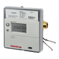
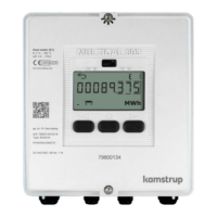
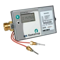
Kamstrup MULTICAL 402 User Manual

Kamstrup MULTICAL 402
32 pages
To Next Page IconTo Next Page
Page #1 background imageLoading...
Page #1 background image
MULTICAL® 402
Cooling meer
Kmstrup A/S · Industrivej 28, Stilling · DK-8660 Sknderborg · T: +45 89 93 10 00 · info@kmstrup.com · kmstrup.com
Insllion nd User Guide
V.I.Trade s.r.o. * Novozámocká 102 * 949 05 Nitra * vit@vit.sk * www.vit.sk * +421 37 6513 665
pobočka Košice * Čermeľská cesta 1 * 040 01 Košice * kosice@vit.sk * +421 55 6321 321

Other manuals for Kamstrup MULTICAL 402

Questions and Answers:

Kamstrup MULTICAL 402 Specifications

General IconGeneral
BrandKamstrup
ModelMULTICAL 402
CategoryMeasuring Instruments
LanguageEnglish

Summary

General Information

Mounting of Temperature Sensors

2.1 Direct sensors

Details on mounting short, direct temperature sensors in various fittings.

2.2 Pocket sensors

Explains the mounting procedure for sensor pockets in pipes.

Information Codes "INFO"

Mounting of Flow Sensor

4.1 Mounting of couplings as well as short direct sensor mounted in MULTICAL®402 flow sensor

Instructions for mounting couplings and direct sensors in the flow sensor.

4.2 Mounting of flow sensor

Details on the orientation and mounting angles for the flow sensor.

Mounting the Calculator

5.1 Wall mounting

Steps for mounting the calculator unit onto a wall using the provided fitting.

5.2 Mounting position of calculator

Guidance on the correct vertical positioning of the calculator relative to the flow sensor.

5.3 Cabling

Illustrates correct and incorrect methods for cabling the meter in humid environments.

5.4 Application at medium temperature, which is less than 5 °C lower than the ambient temperature

Specific installation requirements for medium temperatures below ambient.

Power Supply

6.1 Battery supply

Information on the battery power source, its lifetime, and handling.

6.2 Mains modules

Details on connecting and using mains power supply modules (24 VAC, 230 VAC).

Testing the Function

Electrical Connection

Plug-in Modules

9.1 Pulse inputs

Describes pulse input functionality for connecting external meters.

9.2 Pulse outputs

Details pulse output capabilities for energy and volume.

9.3 Data + pulse inputs, type 402-0-10

Specifies data and pulse input connections for PC interface (Type 402-0-10).

9.4 Data + pulse inputs, type 402-0-11

Specifies data and pulse input connections for PC interface (Type 402-0-11).

9.5 M-Bus + pulse inputs, type 402-0-20

Details M-Bus and pulse input module for data communication.

9.6 M-Bus + pulse outputs, type 402-0-21

Details M-Bus and pulse output module for data communication.

9.7 M-Bus module with MULTICAL® III data packet + pulse inputs, type 402-0-29

Describes M-Bus module compatible with MULTICAL III data packet.

9.8 Wireless M-Bus, type 402-0-30, 402-0-35 + 402-0-37

Covers Wireless M-Bus modules for remote reading systems.

9.9 Radio, type 402-0-40 and 402-0-41

Details radio modules for hand-held reading systems.

9.10 Radio, type 402-0-42 and 402-0-44

Explains radio modules for network and hand-held reading systems.

9.11 Radio, type 402-0-43 and 402-0-45

Details radio modules with pulse outputs for network reading.

9.12 Module overview

Provides a summary of all available communication modules and their types.

Setup via Front Keys

User Guide

Displaying Energy and Consumption Data

Explains displays for consumed energy, legal energy, and water consumption.

Displaying Operational and Temperature Data

Details displays for operating hours, inlet/outlet temperatures, and differential temperature.

Displaying Flow and Capacity Data

Describes displays for actual flow rate and current cooling capacity.

Displaying System and Customer Information

Covers displays for INFO codes, customer number, date, time, serial, and program numbers.

Related product manuals