Do you have a question about the Kamstrup MULTICAL 601 and is the answer not in the manual?
Defines the mechanical environment requirements for installation, such as fixed installation with minimal vibration.
Outlines electromagnetic environment considerations, including separation distances for signal cables.
Details allowed maintenance tasks and the requirement for re-verification after repairs.
Specifies the climatic conditions for installation, including non-condensing environments and temperature limits.
Details the procedures for installing temperature sensors for accurate flow and return temperature measurement.
Explains how to mount sensor pockets in tee-pieces or Y-pieces for optimal sensor placement.
Explains how to interpret error codes displayed on the MULTICAL® 601 for diagnostics.
Specifies how to mount ULTRAFLOW® units up to DN125, including case orientation.
Refers to a separate installation guide for mounting ULTRAFLOW® 54 units with sizes DN150 and larger.
Details mounting for ULTRAFLOW® units DN150 and larger, including case orientation.
Illustrates practical installation scenarios for threaded and flange meters with MULTICAL®/Pulse Transmitter.
Provides guidance on mounting ULTRAFLOW® at a 45° angle in humid environments to prevent condensation.
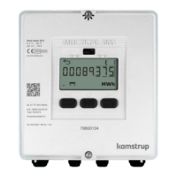
Describes fitting the calculator directly onto the flow sensor using an angle bracket.
Explains mounting the calculator on an even wall using a provided wall bracket.
Details mounting the calculator directly into panels using a specific mounting kit.
Details the use of a D-cell lithium battery, its life, and handling precautions.
Describes connection of protection class II mains modules (24 VAC and 230 VAC) via a two-wire cable.
Details the electrical connections, sensor polarity, and wiring for flow sensors and MULTICAL®.
Provides a visual example of connecting the ULTRAFLOW® to the MULTICAL® using battery supply.
Describes the module for connecting PCs and meters, featuring optocoupler separation.
Details the M-Bus module for network communication, specifying topology and cable requirements.
Explains the radio module for wireless communication, available with internal or external antennas.
Describes a module for pressure transmitters, remote reading, and extra pulse inputs, powered by 24 VAC.
Refers to manual 5512-369 for details on analog output modules.
Refers to manual 5512-396 or 5512-403 for Lon Works modules.
Details the wireless M-Bus module for reader systems, fulfilling C-mode specifications.
Explains the ZigBee module for wireless communication in remote reading systems.
Describes the N2 module for data communication in Johnson Controls Systems.
Provides real time clock and battery backup, recommended for accurate time logging.
Calculates energy difference and includes a time data logger for system analysis.
Features pulse outputs for valve control and an hourly data logger for usage tracking.
Offers a data port for external communication and an hourly data logger for data retrieval.
Ensures compatibility with MULTICAL® 66-C and provides energy/volume pulse outputs.
Enables M-Bus network connection in various topologies with specified cable requirements.
Includes configurable pulse outputs for volume/energy and an hourly data logger.
Calculates volume difference and includes a hourly data logger for open systems.
Simulates cold water temperature via a scheduler for specific temperature sensors.
Features RTC, pulse outputs, and prepares for Kamstrup radio network data transfer.
Wiring instructions for connecting ULTRAFLOW® to MULTICAL®, specifying wire colors and terminals.
Explains the connection process via a Pulse Transmitter for a 3.65 VDC supply.
| Type | Heat Meter |
|---|---|
| Measurement principle | Ultrasonic |
| Pressure Rating | PN16/PN25 |
| Battery life | Up to 16 years |
| Accuracy | Class 2 |
| Communication | M-Bus, Wireless M-Bus |
| Power Supply | Battery |
| Display | LCD |
| Ambient temperature range | 5°C to 55°C |
| Housing material | Brass |
| Application | Heating and Cooling Systems |

