11
7. Operational check
Carry out a operational check when the energy meter has been fully mounted. Open
the thermo-regulators and cocks in order to establish a water flow through the
heating system. Activate the upper push button on the MULTICAL® 601 and check
that the display values for temperature and water flow are reliable.
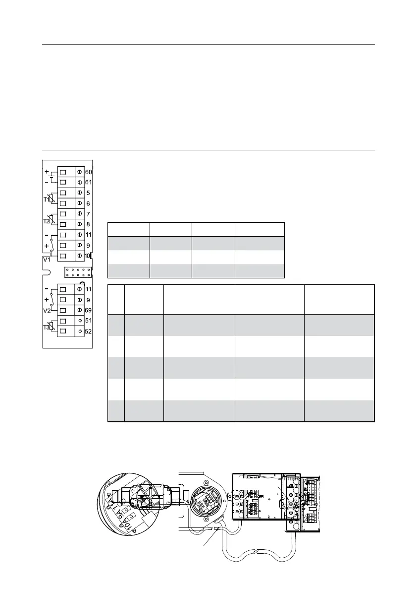
8. Electrical connection for MULTICAL® and
ULTRAFLOW®
The polarity of the temperature sensors T1, T2 and T3 is
unimportant. Use below colours at the flow sensors V1 and V2
when connecting the ULTRAFLOW® and electronic pick-up units.
Flow sensors with Reed switch output must be connected to
terminals 11-10 and 11-69, respectively.
V1 V2
-
11 11 Blue
+
9 9 Red
SIG
10 69 Yellow
Terminal
No.
Standard
measurement of
heat and cooling
Heat measurement
and leak surveil-
lance
Energy
measurement
in open systems
T1 5–6
Sensor in flow pipe
(red)
Sensor i flow pipe
(red)
Sensor in flow pipe
(red)
T2 7–8
Sensor in return pipe
(blue)
Sensor in return pipe
(blue)
Sensor in return pipe
(blue)
V1 11–9–10
Flow sensor in
flow or return pipe
Flow sensor
in flow pipe
Flow sensor
in flow pipe
V2 11–9–69 -
Flow sensor
in return flow pipe
Flow sensor
in return pipe
T3 51–52 -
Tank/heat exchanger
temperature
Reference sensor
(grey)
8.1 Connection example
Example of connection between ULTRAFLOW® and MULTICAL® (battery supply).
ø4...6 mm
M16, ø4...9 mm