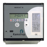
The MAXICAL® III is an energy meter designed for measuring, calculating, and registering energy consumption in large heat installations where water is the heat transferring agent. It is typically used for main heat metering at CHP (cogeneration heat and power) suppliers, and for heat metering through transmission networks or exchange stations.
Function Description
Beyond energy metering, the MAXICAL® III offers various other functions, including the display of prevailing and peak values, relay, pulse, and analogue outputs, tariff registering, and data communication. These features make it suitable for industrial management and regulation applications.
Thermal energy calculation is based on the differential temperature measured across the flow and return pipes and the volume of water. The device automatically corrects for density and enthalpy. Temperature measurement uses a 4-wire technique to ensure optimal accuracy and reliability.
The flow meter input includes galvanically connected stages for electronic pick-ups and galvanically isolated stages for flow meters with active outputs up to 5 or 10 kHz. All operating parameters can be programmed via an optical eye on the front of the meter and a computer with a Windows software package (type 66-99-210) for quick and simple setup.
The MAXICAL® III features several tariff functions. Regardless of the tariff type, total thermal energy is always accumulated in the primary register. Additionally, tariff registers TA2 and TA3 accumulate energy consumed under specific conditions, defined by relevant limit values (TL2 and TL3). These conditions can be configured using the Windows software.
The device's capabilities can be expanded with plug-in modules. There are two module spaces:
- The upper space can accommodate a module with 4 active analogue outputs for flow, power, flow temperatures, and return/differential temperature. This module also includes two relay outputs: a programmable limit switch and an information code switch.
- The bottom space is designed for M-Bus, telephone modem, or EcheLon modules.
Important Technical Specifications
- Display: Liquid crystal display with 8 numerical digits and 3 alphanumerical characters. 7 digits show current and accumulated values, while the last three indicate the unit or symbol. It has a discreet background light for visibility in poor lighting.
- Temperature Measurement: Measures flow and return temperatures between 0.01°C and 182.00°C. Temperatures outside these limits are registered as sensor faults after 10-20 minutes. The differential temperature is accurately calculated across the entire measuring range, even down to 0.01°C, though accuracy is slightly affected below Dt=3°C. Negative differential temperatures are perceived as 0.00°C, stopping energy registration.
- Temperature Sensors: Supports Pt100 or Pt500 sensors (IEC 751 standard). Sensors must be matched, and a 4-wire screened cable should be used for connection to ensure optimal precision. The cable screen must be connected at the MAXICAL® III, not at the sensor housing. For large diameter pipes, average measuring can be achieved with 5 Pt100 sensors in series (for Pt500 input) or 4 sensors in parallel/series.
- Cable Specifications for Temperature Sensors: Cross-sectional area of at least 0.5 mm² is recommended when the difference in length between flow and return sensor cables is up to 10 m for Pt100 or 50 m for Pt500 sensors.
- Flow Meter Input (Terminals 9-11): Used for mechanical meters with Reed-switch output, mechanical meters with electronic pick-ups, or Kamstrup Energi's ULTRAFLOW® II ultrasonic meters. The flow meter must use MAXICAL® III's pulse separation (CCC-table). Pulse duration must be > 0.5 msec, and intervals between pulses > 10 msec. Input frequency must not exceed 100Hz. Max cable length: 5m.
- Flow Meter Input (Terminals 75-76): Galvanically separated via an optocoupler, designed for electronic flow meters with active frequency output of max. 5 kHz or 10 kHz. Frequency output amplitude: 12-30V. Pulse duration: at least 30 msec. Max cable length: 50m.
- Pulse and Data Outputs (Terminals 16-19, 62-64): Pulse outputs for energy and water (16-19) normally emit one pulse per display count (e.g., 0.01 MWh, 0.1 m³). A 10:1 divider can be programmed. Data outputs (62-64) are used for reading daily data, target date, verification data, and programming. Communication is passive/serial at 1200 Baud, connectable to a computer's COM-port via a data cable (type 66-99-106).
- Analogue Outputs (Terminals 80-87): Four active 4-20 mA outputs, capable of bearing a load of 0-500Ω. Used for remote display and registration. The fourth output (86-87) can be programmed as return line or differential temperature. All outputs have 4 mA corresponding to zero, with programmable measuring ranges.
- Relay Outputs (Terminals 88-93): Used for monitoring process and integrator. Infocode is connected between 92 and 93 when voltage supply is normal and no system error (info = 000). If an info code > 000 is registered (e.g., faulty sensors, power interruption), the relay switches to 91-92. The relay limit is a programmable limit switch for power, flow rate, flow temperature, return temperature, or differential temperature. When the measured value exceeds the limit, the relay energizes, closing the contact between 89 and 90. Load on relay contacts must not exceed 100 V AC/DC and 500 mA.
- Voltage Supply: 230 V AC. Live and neutral connected to terminals 28 and 27. No earth wire connection needed due to double insulated transformers.
- Back-up: Integrated 1 Ah lithium cell for continuous supply to the internal clock (with date) during power cuts. No back-up for frequency input (75-76), but 5-minute back-up for pulse input (10-11).
- Permanent Memory (EEPROM): Stores all accumulated values hourly. At midnight, the following data is stored in a 31-day datalogger: Date, Energy, Water, TA2, TA3, Alarm, Peak time, and Peak power/flow.
- Information Codes: During normal operation, the info code is 000. Faults display an "E" and de-energize the Infocode relay. Codes are additive if multiple faults occur. Examples: +2 (flow meter connection), +4 (return temperature sensor), +8 (flow temperature sensor), +256 (excess water pulses).
- Optical Data Acquisition: Infrared receiver/transmitter on the front panel for serial data communication (IEC 1107/EN61107). Used with optical read-out head (type 66-99-102) for data acquisition and programming.
Usage Features
- Display Navigation: Use right or left keys to move between displayed values. Only configured values are shown. The display automatically reverts to accumulated energy consumption after approx. 8 minutes of inactivity.
- Programming: All operating parameters can be programmed via the optical eye and a computer with Windows software (66-99-210). Programming is divided into PROG (legal measuring parameters, only changeable when program block V=0), CONFIG (display, tariff, alarm), and DATA.
- Tariff Functions: Supports power-controlled, flow-controlled, cooling, return temperature, average temperature, remote-controlled, and time-controlled tariffs. Tariff limits (TL2, TL3) are configured via software.
- Alarm Output: Configurable for power-controlled, flow-controlled, cooling, flow temperature, or return temperature alarms, with programmable alarm limits (AL).
- Pulse Dividers: Configurable pulse dividers for energy and water outputs (1:1 or 10:1).
- Data Communication: Data strings can be read via optical read head or terminals 62-63-64. Supports EN61107 requests for various data types (normal data, read-out data, verification data, daily data).
- Software Requirements: IBM-compatible 486 or Pentium computer with at least 8 MB RAM (16 MB recommended), 10 MB free hard disk space, 3½" (1.44 MB) floppy drive, mouse, free serial COM port, free parallel port for label printer. Windows 3.1, 3.11, or 95. Min. VGA monitor.
- Programming Modes: Partial programming (V=1) allows changes to non-legal measuring data. Total programming (V=0) allows changes to all measuring parameters.
- Verification: Quick-figure (highest resolution) can be read from the display (as T-M) or data output. The Quick-figure cannot be reset directly but is calculated as the difference before and after verification. Energy calculation during verification is critical for determining meter deviation.
Maintenance Features
- Installation Requirements: Must be installed in an area with ambient temperature between 0°C and 55°C. Signal cables must be laid individually, separated from supply/mains cables by at least 25 cm. COMBITEMP sensors for direct installation only if flow velocity < 3m/sec; otherwise, sensor pockets must be used.
- Information Code Reset: Information codes can be reset via the optical read-out head, data terminals 62-63-64 (M3 instruction), or by activating both front plate buttons for 10 seconds until "Call" appears.
- Battery Replacement: Internal lithium back-up cell should be replaced every 8 years (or 2 years if average ambient temperature > 35°C). Spare part no. 1606-047. Requires disconnecting power, removing the back plate, and desoldering the old cell. The internal clock must be reset after replacement.
- Module Insertion: Analogue and relay modules (66-x0) can be fitted into existing MAXICAL® III units. Requires removing the back panel and cutting connection holes. The module must be programmed after installation.
- Total Reset: The meter can be totally reset by removing the back plate, taking out the main PCB, and then replacing the PCB while simultaneously pressing both front panel keys. This will cancel energy, water, hour counter, and info codes.
- Troubleshooting Guide: Provides solutions for common issues such as blank display, high temperature readings, no energy accumulation, incorrect accumulation, faulty temperature display, and insufficient analogue output current.
- Sealing: All verified meters are sealed after installation to prevent tampering. The integrator, flow part, and temperature sensors are independently sealed. The front panel can be locked and sealed with thread and a plastic seal. DIN-head temperature sensors (shape B) can be sealed to prevent removal. Sensor pockets and flow meters should also be sealed as prescribed.
- Disposal: Kamstrup can dispose of worn-out meters correctly if agreed upon, with the customer covering transport. Alternatively, customers can dispose of meters by removing the lithium battery for approved destruction and sorting other components (coppered epoxy laminate, aluminium, plastic, cardboard) for recycling.