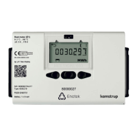
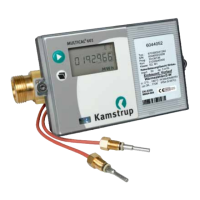
Do you have a question about the Kamstrup MULTICAL 602 and is the answer not in the manual?
Defines operational limits and measurement ranges for the calculator and sensors.
Specifies environmental conditions like vibration for sensor installation.
Details electromagnetic compatibility requirements for meter installation.
Outlines permissible ambient temperature and humidity for operation.
Describes procedures for replacing components and repair requirements.
Identifies the specific Kamstrup battery type for replacement.
Instructions for installing pocket-type temperature sensors.
Guidance on mounting short direct temperature sensors.
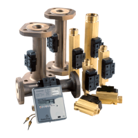
Procedures for installing ULTRAFLOW® sensors up to DN125.
Installation guidelines for ULTRAFLOW® 54 sensors from DN150.
Visual examples demonstrating flow sensor installation configurations.
Describes direct mounting of the calculator onto the flow sensor.
Details mounting the calculator on a wall using a fitting.
Explains how to mount the calculator in panels or control panels.
Illustrates typical wiring for ULTRAFLOW® and MULTICAL® with battery supply.
Shows electrical connection for heat meters using two flow sensors.
Details the connection of a Pulse Transmitter for ULTRAFLOW® 54.
Information on the built-in lithium battery power source for MULTICAL® 602.
Describes power supply options using 24 VAC or 230 VAC mains modules.
Details isolated linear supply modules for 24 VAC and 230 VAC.
Overview of top modules for extending MULTICAL® 602 functionality.
Description of base modules that add functions like data and pulse inputs.
Explains how the MULTICAL® 602 measures energy consumption.
Describes the various readings and information shown on the meter display.
| Flow Sensor | Ultrasonic |
|---|---|
| Display | LCD |
| Battery Life | Up to 16 years |
| Communication | M-Bus, Wireless M-Bus |
| Approval | MID class 2, EN 1434 |
| Accuracy | Class 2 |
| Pressure Rating | PN16 |
| Application | Heating and cooling systems |
| Temperature Range | 0°C to 180°C |
