14 Kamstrup A/S • 5512952_C6_GB_07.2015
MULTICAL® 602 & ULTRAFLOW®
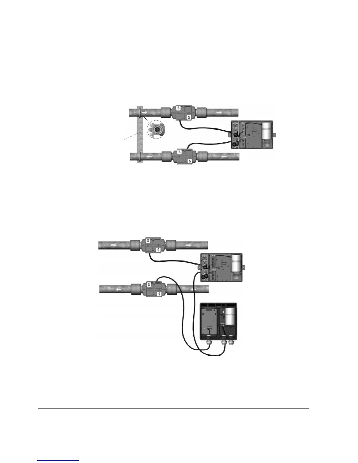
5.2 Het meter with two flow sensors
MULTICAL® 602 cn be used in vrious pplictions with two flow sensors, including lek
surveillnce nd open systems. When two ULTRAFLOW® re direct connected to one
MULTICAL® 602, close electric coupling between the two pipes ought to be crried out s min
rule. If the two pipes re instlled in het exchnger close to the flow sensors, however, the het
exchnger will provide the necessry electric coupling.
ULTRAFLOW® 54 (H)
MULTICAL® 602
Electricl connection
ULTRAFLOW® 54 (H)
• Inlet nd outlet pipes re closely electriclly coupled.
• No electric welding occurs.
In instlltions where the electric coupling is not possible or welding in the pipe system cn occur,
the cble from one ULTRAFLOW® must go through Pulse Trnsmitter with glvnic seprtion
before the cble enters MULTICAL® 602.
ULTRAFLOW® 54 (H)
MULTICAL® 602
Pulse Trnsmitter
ULTRAFLOW® 54 (H)
• Inlet nd outlet pipes re not necessrily closely coupled.
• Electric welding* cn occur.
* Electric welding must lwys be crried out with the erth pole closest to the welding point.
Dmge to meters due to welding is not comprised by our fctory wrrnty.