12 Kamstrup A/S • 5512952_C6_GB_07.2015
MULTICAL® 602 & ULTRAFLOW®
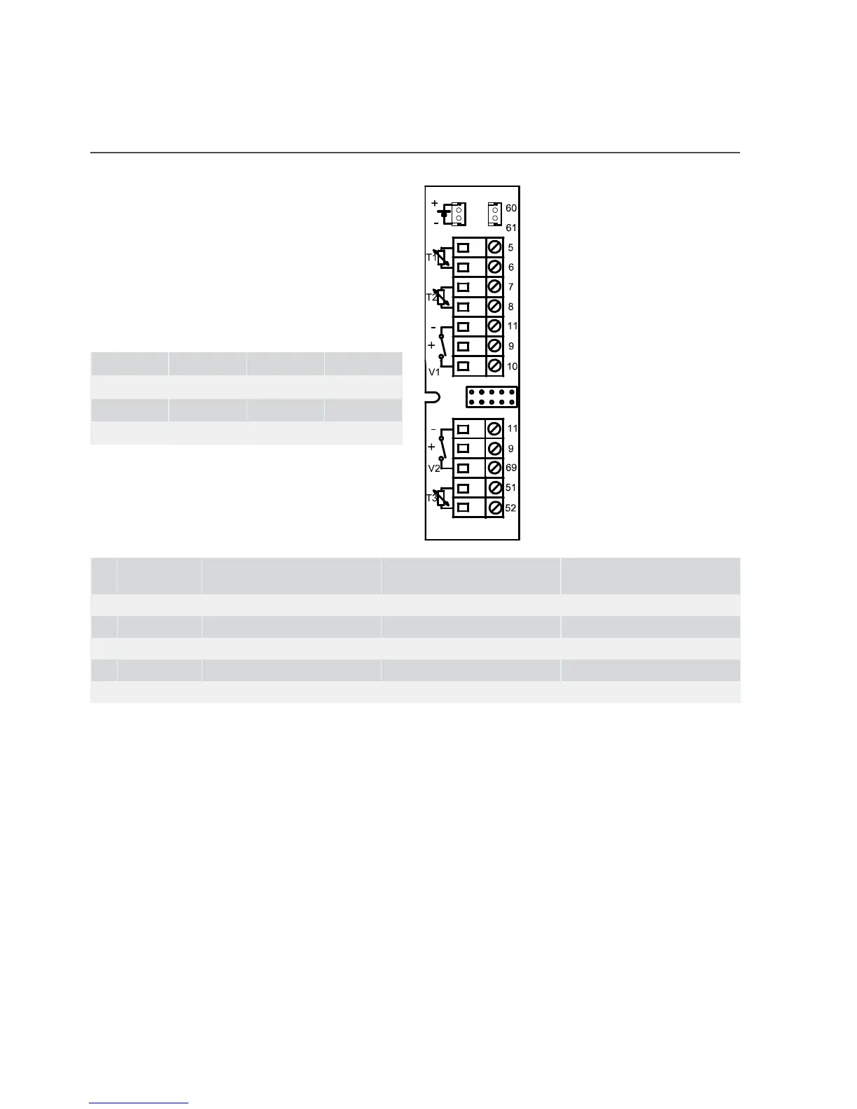
5 Electricl connection, MULTICAL® nd ULTRAFLOW®
The polrity of temperture sensors T1, T2 nd
T3 is unimportnt.
For flow sensors V1 nd V2 the below-
mentioned colours re used when connecting
ULTRAFLOW® nd electronic pick-up units.
Flow sensors with reed switch output re
connected to terminls 11–10 nd 11–69
respectively.
V1 V2
- 11 11 Blue
+ 9 9 Red
SIG 10 69 Yellow
Terminl no. Stndrd het nd cooling
mesurement
Het mesurement nd lek
surveillnce
Energy mesurement in
open systems
T1 5-6 Sensor in inlet (red) Sensor in inlet (red) Sensor in inlet (red)
T2 7-8 Sensor in outlet (blue) Sensor in outlet (blue) Sensor in outlet (blue)
V1 11-9-10 Flow sensor in inlet or outlet Flow sensor in inlet Flow sensor in inlet
V2 11-9-69 - Flow sensor in outlet Flow sensor in outlet
T3 51-52 - Tnk/exchnger temp., if ny Reference sensor (grey)