7Kamstrup A/S • 5512952_C6_GB_07.2015
MULTICAL® 602 & ULTRAFLOW®
3 Mounting of flow sensor
Prior to instlltion of the flow sensor, the
system should be flushed nd protection
plugs/plstic diphrgms removed from the
flow sensor.
Correct flow sensor position (inlet or outlet)
ppers from the front lbel of MULTICAL® 602.
The flow direction is indicted by n rrow on
the flow sensor.
Fittings, if supplied, cn only be used for PN16.
For PN25 instlltions, fittings suitble for
PN25 should be used.
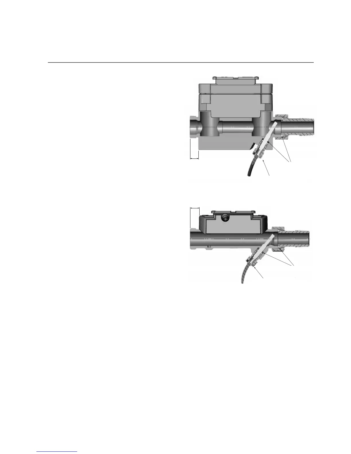
In connection with G¾x110 mm nd G1x110
mm it shll be checked tht the thred run-out
is sufficient. See the figures to the right.
Tightening pp. 4 Nm
Gsket
10 mm
Type 65-5-XXAX-XXX
Gsket
Tightening pp. 4 Nm
12 mm
Type 65-5-XXHX-XXX
Couplings nd gskets re mounted s shown in the bove figures.
Stright inlet: ULTRAFLOW® requires neither stright inlet nor stright outlet to meet the
Mesuring Instruments Directive (MID) 2004/22/ EC, OIML R75:2002 nd EN 1434:2007. A stright
inlet section will only be necessry in cse of hevy flow disturbnces before the sensor. We
recommend to follow the guidelines of CEN CR 13582.