Do you have a question about the Kane KANE900 Plus and is the answer not in the manual?
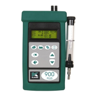
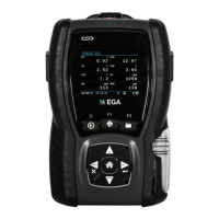
Describes the analyser's front panel buttons, ports, and indicators.
Details the connections and labels found on the rear panel of the analyser.
Illustrates the standard probe, including thermocouple and depth stop cone.
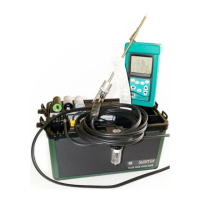
Shows how external components like the particle filter and water trap connect.
Pre-operation checks to ensure the analyser and its components are ready.
Explains the process of zeroing sensors using fresh air before operation.
Introduces the different screen display modes available on the analyser.
Details navigation and data display within the 4-line per page format.
How to customize the display by scrolling through parameters line by line.
Describes viewing 8 parameters simultaneously across the display.
Best practices for inserting the probe into the flue for accurate measurements.
Instructions for connecting the probe to measure flue draught and pressure.
Essential checks to maintain analyser performance and safety during use.
Step-by-step procedure for safely powering down the analyser.
Information on EMC compliance and testing procedures for the instrument.
Overview of navigating the analyser's menu system and performing basic functions.
Details the primary sub-menus available for analyser configuration and settings.
Explains how to select and configure various operational parameters for the analyser.
How to change the units of measurement for displayed parameters.
Configuration options for the analyser's screen display settings.
Customizing analyser settings like language, alarms, and date/time.
Programming custom text, like company name, for printout headers.
Instructions for printing real-time data from the analyser.
Example of the data format and content generated by the analyser's print function.
Procedure for saving current test readings into the analyser's memory.
How to access and print previously saved test results.
Instructions on how to remove stored test data from the analyser's memory.
Method for storing three consecutive readings to calculate an average.
How to review the stored samples and their calculated average value.
Procedure for printing the results of the average of three readings.
Steps to maintain the water trap for proper analyser function.
Procedure for replacing the filter to protect the analyser's sensors.
Explains the meaning of each parameter shown on the analyser's main screen.
Details the formulas and methods for calculating combustion efficiency.
Provides methods and examples for calculating fuel-specific data for the analyser.
Official statement on the product's compliance with EMC standards.
| Type | Flue Gas Analyzer |
|---|---|
| O2 Sensor Range | 0 to 21% |
| Power Source | Rechargeable Battery |
| Display | Color LCD |
| Data Logging | Yes |
| Battery Life | 8 hours |
| Measures | CO, O2, Temperature, Pressure |
| Calculates | CO2, Efficiency, Excess Air |
| Connectivity | Bluetooth |
| Measurement Range | Depends on the parameter |
| Resolution | 1 ppm (CO), 0.1% (O2) |
| Response Time | Depends on the parameter |