Do you have a question about the Kane KM940 and is the answer not in the manual?
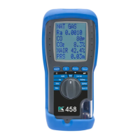
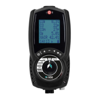
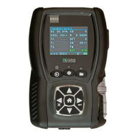
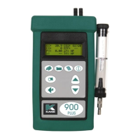
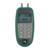
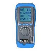
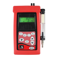
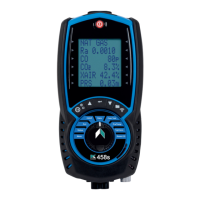
Details about the analyzer's front panel, buttons, and display.
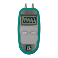
Describes the rear view of the analyzer, including sensor labels and serial number.
Illustrates the components and arrangement of the standard flue gas probe.
Shows how the various components connect to the analyzer unit.
Pre-start checks to perform before each use of the analyser.
Procedure for the analyser's automatic zero calibration sequence.
Describes the display format showing 4 lines of data per page.
Allows customization of the display to show desired data lines.
Explains the display mode showing 8 parameters on 4 lines.
How to access and navigate the main menu and sub-menus.
Details the structure of the main menu with its sub-menus.
How to select and configure fuel type and other parameters.
How to change units for temperature, gas, pressure, and efficiency.
Options for controlling display features like light, mode, and contrast.
Configuration of language, calibration time, alarms, date, and header.
How to print current measurement data directly from the analyser.
Example of the data format produced by the standard printout.
Steps to save current test data into the analyser's memory.
Methods for accessing and printing previously saved test data.
Procedure for removing stored test data from the analyser's memory.
How to safely empty and clean the water trap component.
Instructions for replacing the particle filter to protect sensors.
Detailed explanation of each parameter shown on the main display.
Explains the basis and methodology for calculating combustion efficiency.
Details how to calculate fuel data for use with the analyser.
Statement regarding the product's compliance with EMC directives.
| Power Source | Rechargeable Battery |
|---|---|
| Display | LCD |
| CO2 Range | 0-20% |
| Resolution O2 | 0.1% |
| Resolution CO | 1ppm |
| Resolution CO2 | 0.1% |
| Measures | CO, O2, CO2, Temperature |
| Accuracy O2 | ±0.2% |
| Accuracy CO | ±5ppm <100ppm, ±5% >100ppm |
| Storage Temperature | -20°C to 60°C |