Do you have a question about the Kane 905 and is the answer not in the manual?
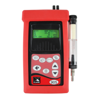
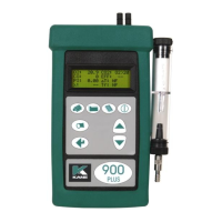
Measures Temperature, Pressure, O2 and CO as standard. Stores 150 sets of test results. Output to IR Printer (optional).
Lists available sensor options and upgrades like High Range CO sensor, NO sensors, NO2 sensor, SO2 sensor, Wireless upgrade, and Teflon Hose.
Details the physical features of the analyser, including connectors, ports, screen, and keypad buttons with their functions.
Illustrates the rear view of the analyser, showing sensor fittings, exhaust port, charger socket, and serial number label.
Diagram showing the standard probe assembly, including thermocouple, stainless steel shaft, depth stop cone, gas path, and thermocouple wire.
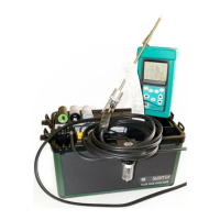
Details the various connection points on the analyser, such as optional inlet temperature probe, gas connection, particle filter, water trap, and flue temperature connector.
Warns about toxic combustion gases, requiring use in well-ventilated areas by trained personnel, and recommends 'bump' checks for detectors.
Details the analyser's classification as Class III equipment and the battery charger's designation, including operating conditions like temperature and humidity.
Instructs on initial battery charging for 12 hours and selecting initial analyser settings like language, calibration time, CO gas alarm, and date/time.
Emphasizes the importance of reading the manual fully and being aware that purchased configuration might not support all features detailed.
Lists checks before switching on: particle filter, water trap, connections, sampling ambient air, water trap fitment, and flue temperature connection.
Describes the automatic calibration process where the analyser purges fresh air for sensor zeroing (toxic) and O2 setting to 20.9%.
Explains obtaining quoted specifications, fuel selection display, zeroing toxic sensors, and introducing the main display with parameter options.
Details the main display options: 4 Page Mode, Line Scroll Mode, and 8 Page Mode, allowing users to customize displayed parameters.
Explains how to navigate and view data in the 4 Page Mode, detailing the content of pages 1-6 and the function of the backlight button.
Describes Line Scroll Mode customization and 8 Page Mode parameter display, including how to change the bottom display line.
Details how to insert the probe into the flue for sampling, recommended positioning, and the use of the depth stop cone for different flue diameters.
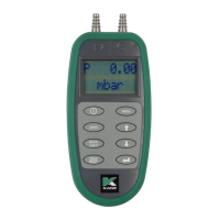
Explains how to take pressure readings and flow readings, including unit settings and requirements for accurate measurements.
Outlines crucial regular checks during sampling: probe temperature limits, analyser internal temperature, avoiding hot surfaces, and monitoring the water trap.
Provides instructions for safely shutting down the analyser, including removing the hot probe, allowing it to cool, and pressing the ON/OFF button.
Presents the overall menu structure (SELECT, UNITS, DISPLAY, SETUP) and explains basic navigation using keypad buttons.
Explains basic menu navigation using the keypad buttons (MENU, UP, DOWN) to access and move through the main menu options.
Details how to access selected menu items, select parameters, and change settings using navigation keys and the ENTER button.
Explains how to save settings and return to the MAIN MENU using the ENTER key, and how to return to the MAIN DISPLAY.
Introduces the MAIN MENU and its four sub-menus: SELECT, UNITS, DISPLAY, and SETUP, and how to access and navigate them.
Details the 'SELECT' sub-menu, covering FUEL selection for boilers and setting the PITOT value, including fuel constants.
Explains the 'O2 Ref' setting in the SELECT menu, discussing how it references toxic gas measurements to defined oxygen levels.
Details the 'SMOKE' setting for smoke test numbers and the 'RESET' function to zero sensors without turning off the analyser.
Covers the 'UNITS' sub-menu, allowing changes to displayed units for Temperature, Gas, Pressure, and Efficiency.
Explains the 'DISPLAY' sub-menu options: LIGHT, MODE (4/8 Page, Line Scroll), and CONTRAST adjustment.
Introduces the 'SET UP' sub-menu, listing parameters like Language, Auto calibration, CO alarm, NOx%, Date/time, Header, and Printer type.
Details 'LANG' for language, 'ZERO' for autocalibration time, and 'NO REF' for Nitric Oxide units.
Explains 'CALENDAR' for changing date/time and 'FORMAT' for date display/printing settings.
Details 'HEADER' programming for custom text on printouts, including character selection and movement.
Covers 'CO ALARM' setting for CO reading levels and 'PRINT' option to change the printer type.
Describes optional infra-red thermal printers and wireless modules for data communication with PCs and mobile devices.
Guides on how to print live test data on request by pressing the PRINT button while the analyser shows the MAIN DISPLAY.
Shows an example of the standard printout format and lists software compatibility for the KANE905 with Android and PC.
Explains how to store live test data by accessing the STORE menu, selecting 'STORE' mode, and pressing 'STORE' to log readings.
Details how to view or print stored test data by selecting 'VIEW / PRINT' in the STORE menu and specifying the location range.
Provides instructions on deleting stored data by selecting 'DELETE' mode in the STORE menu and confirming the action.
Describes the 'Ave Store' function for storing up to three samples for averaging, including countdowns and viewing the stored samples.
Details how to print the average readings, noting that any reading flagged as 'NOT FITTED' will be omitted from the printout.
Instructs on regular checking and emptying of the in-line water trap, warning about potential acidity of condensate.
Explains the importance of changing the particle filter to protect the pump and sensors, and the procedure for replacement.
Lists common instrument fault symptoms such as 'Oxygen too high', 'Analyser not holding charge', and 'Analyser does not respond', with potential causes.
Recommends annual servicing and re-certification of the analyser to eliminate long-term sensor and electronics drift, and advises checking local regulations.
Details technical specifications for parameters like Temp Measurement, Gas Measurement, Pressure, CO2, Losses, and Efficiency with resolution, accuracy, and range.
Defines parameters shown on the main display, including DATE, TIME, BATTERY, NETT, O2, CO, EFF (G), CO2, FLUE (Tf), and INLET (Ti).
Defines more main display parameters: CO/CO2 Ratio, P INDEX (Poison Index), XAIR (Excess Air), FLOW, PRS (Pressure), and NO (Nitric Oxide).
Defines NOx, SO2, and O2 reference parameters, explaining their calculation, display conditions, and referencing methods.
Explains that the efficiency calculation is based on British Standard BS845, identifying three sources of loss associated with fuel burning.
Details the formulas for calculating Gross Calorific Value (Qgr), Net Calorific Value (Qnet), constants (K1, K2, K3, K4), and various efficiency components.
Presents formulas for Net Efficiency, Gross Efficiency, Excess Air, CO2%, and Unburned fuel Loss %, including the Oxygen Reference formula.
Provides an example calculation for fuel data, including chemical composition, calorific values, and constants for efficiency calculations.
Shows how to program calculated fuel values into the analyser, listing the required constants for fuels like Natural Gas and Wood.
Details the analyser's compliance with European Council Directive 89/336/EEC regarding electromagnetic disturbances and immunity, listing applicable standards.
Offers guidance on checking for and minimizing electromagnetic interference during operation, suggesting adjustments to meter position or equipment.
Provides information on the Waste Electrical or Electronic Equipment (WEEE) Directive for responsible processing and recycling of the product.
A note advising that batteries used in the instrument should be disposed of in accordance with current legislation and local guidelines.
| Brand | Kane |
|---|---|
| Model | 905 |
| Category | Measuring Instruments |
| Language | English |