74
Hardware Information
Precautions
The KAM Plus is grounded through its connections to your transceiver. Make sure your transceiver
is properly grounded and your computer has equal ground potential. Follow the grounding instruc-
tions in your transceiver manual.
Cables provided with your KAM Plus are shielded. If you use other cabling, be certain it is shielded.
We do not recommend the use of unshielded RS-232 ribbon cable in an amateur radio environ-
ment.
The supplied serial cable contains all 25 wires and is designed to be used with your KAM Plus. Be-
fore using this cable with any other equipment, you should check your equipment manuals to de-
termine that no damage will result.
Connecting to the Computer
The KAM Plus serial port is shipped from the factory configured to communicate with your com-
puter using RS-232 signaling. This is compatible with PC compatible computers, Macintosh, dumb
terminals, and most other terminal devices. The Commodore 64, however, requires TTL signaling
as do a few other computers. If your computer requires TTL, you may configure your KAM Plus to
use these signals by placing jumper K7 on the center post and the post marked TTL (toward the
rear of the KAM Plus), See the assembly/disassembly instructions in this manual.
Cable Wiring
ALL Kantronics software uses a minimum of five wires between the computer and the KAM Plus.
The pins that must be connected from the KAM Plus to your computer for these programs are
TXD, RXD, SG, RTS and CTS. (See chart below.) You may optionally choose to connect the DSR,
DTR. and DCD pins, however these are not used by Kantronics programs or by the KAM Plus.
Some terminal programs do not support hardware flow control, and will fail to operate if these
lines are connected – refer to your software manual to determine the capabilities of your program.
If your program does not support hardware flow control, you should connect only the TXD, RXD
and SG pins from the KAM Plus to your computer.
Still other terminal programs require the presence of a signal on the DSR pin in order to operate. If
your program requires this, connect the DTR and DSR pins on your computer end of the cable to-
gether with a jumper.
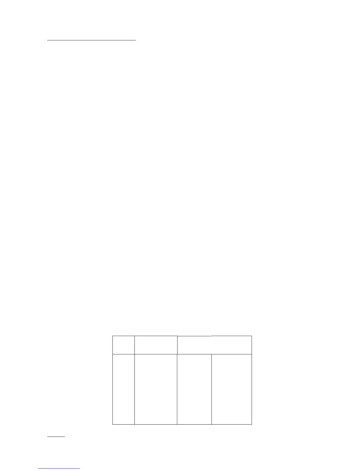
The KAM Plus serial port (computer) connector has 25 pins, which are configured as:
Pin
Name
KAM Plus
Pin Number
Computer
(DB9)
Pin Number
(DB25)
FG
TXD
RXD
RTS
CTS
DSR
SG
DCD
DTR
1
2
3
4
5
6
7
8
20
N/A
3
2
7
8
6
5
1
4
1
2
3
4
5
6
7
8
20
NOTE: FG (Frame Ground) and SG (Signal Ground) are tied together in the KAM Plus.