Operating instructions multicomp
Version 1.00 Page 27 of 29
EDEBDA0144 / 0511-1 GB
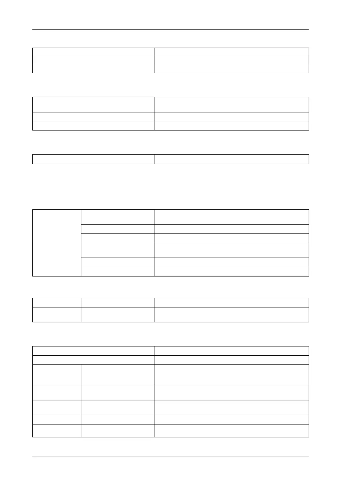
11.4 Device memory
11.5 Other limits
11.6 Power supply
11.7 Hardware inputs and outputs
11.7.1 Hardware inputs
Measuring input for
voltage
U
PH-N
or
U
PH-PH
30V ... 690V ... 790V AC
Direct impedance 750 kOhm
Measuring range 1 measuring range, measurement voltage transformer programmable
Measuring input for
current
I
L1
or I
L2
or I
L3
0.015A ... 5A ... 6A AC
Power consumption ≤ 2VA at 6A
Measuring range 1 measuring range, current transformer programmable
11.7.2 Hardware outputs
Alarm relay Switching capacity 250 V (AC) / 2 A potential-free
Capacitor
stage relay
Switching capacity 250 V (AC) / 2 A potential-free
11.8 Electrical connection
Data storage 16 kB RAM volatile
Program and parameter memory 128 kB flash
Extreme values (Max.) Missing compensation power Q
max
Limit violations: acquisition time
harmonics
approx. 100 ms
Overvoltage disconnect: acquisition time approx. 40 ms
No voltage disconnect: acquisition time approx. 40 ms (for measurement voltage)
Power supply 85 to 265V AC/DC; max. 12 VA, 6 W
Connection elements Plug-in terminals
Permissible cross section of the connection lines 2.5 mm
2
Measurementmeasur
ement current voltage
inputs
Fuse protection max. 6 A
measurement current
input
Fuse protection NONE!!! Always short-circuit current transformer terminals k and l
prior to opening the circuit!
Input
Control voltage
Fuse protection max. 6 A
Relay output Fuse protection max 2 A medium time-lag
Transformer
connection
Connections See connection chart