GB - 11
COMBICONTROL
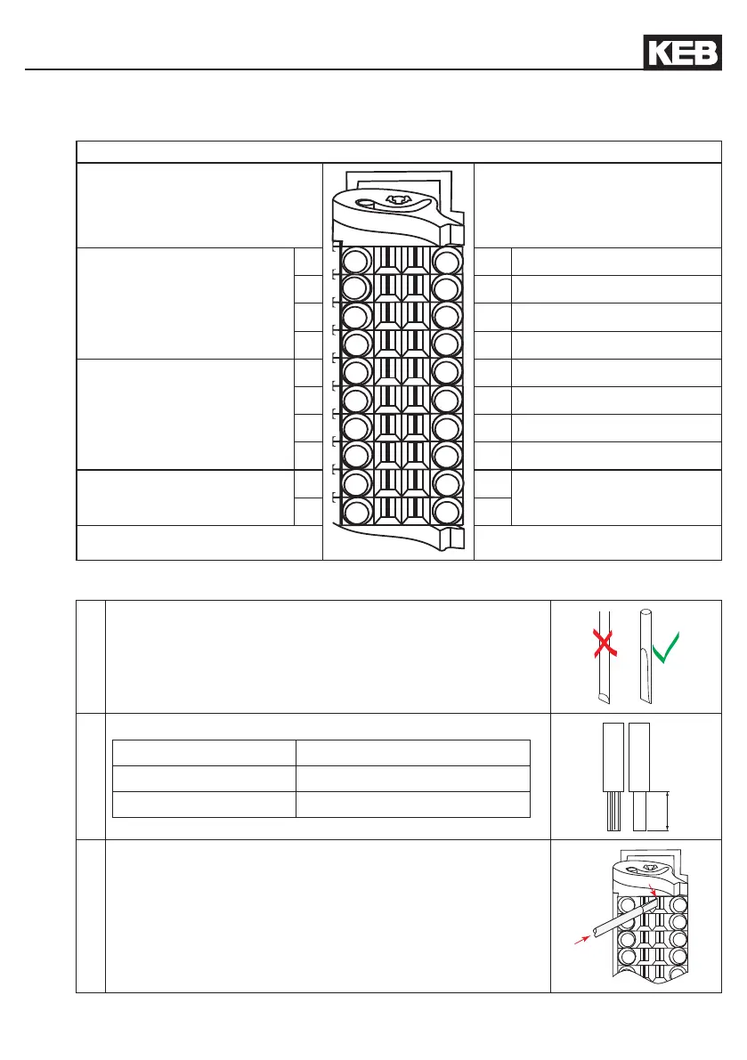
2.3 Voltage supply and digital inputs and outputs
Figure 2.3 Socket X2
Voltage supply Digital inputs and outputs
+ Voltage input (UM)
(internally interconnected)
1 11
Digital input 0
2 12
Digital input 1
3 13
Digital input 2
4 14
Digital input 3
- Voltage input (UM)
(internally interconnected)
5 15
Digital output 0
6 16
Digital output 1
7 17
Digital output 2
8 18
Digital output 3
+ Voltage input (US)
9 19
PE
- Voltage input (US)
10 20
2.3.1 Assembly of the wires
Required tools:
Screw driver
SD 0,4 x 2,5 (DIN 5264)
1. Strip cable
Cable permissible cross-section
exible 0,2…1
mm2
Wire-end ferrule 0,13…0,34
mm2
2. Plug screw driver into the square slot to the midside

 Loading...

