3.2.2
PFH 2.6 • 10
-12
1/h
PFD 2.3 • 10
-7
on demand
Proof-Test-Interval T 20 years
ForSILclassicationinconnectionwiththe applicationsconsiderthe failureratesof theexternal
switchdevicesfornalevaluation.
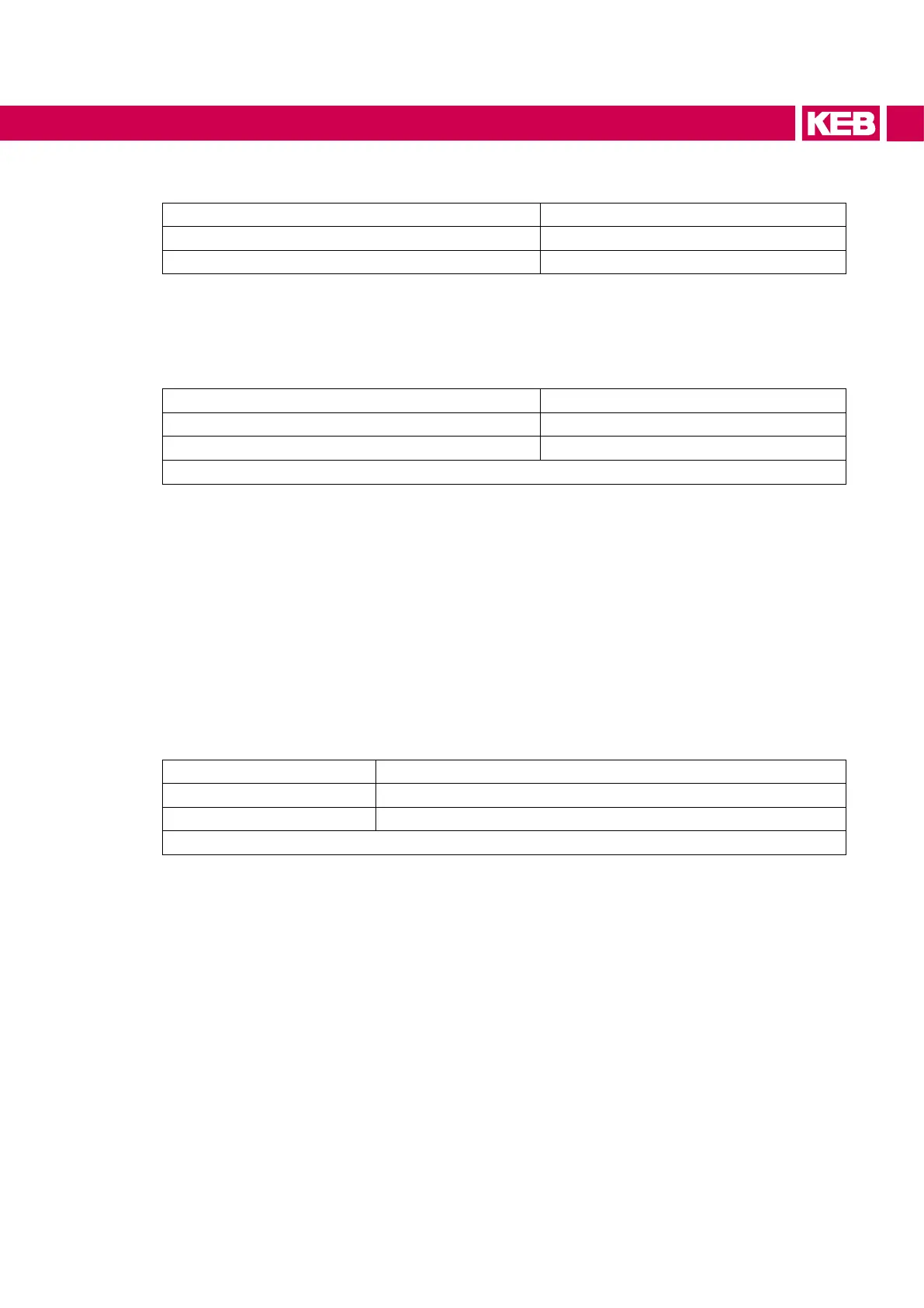
3.2.3
Category 4
MTTF
D
>1000 years
DC high
Table 3: Classications of STO
Fortheclassicationwithinaperformancelevelinconnectionwiththeapplicationsconsiderthe
failureratesoftheexternalswitchdevicesfornalevaluation.
3.3 Safe brake control (Safe Brake Control – SBC)
The safety module type1 can safety control an external brake. The circuit operates on two channels.
Thereby brake release is only possible by the control in the COMBIVERT if both inputs are supplied
(SBC inputs see chapter 4).
The two channels are realized with a diverse high-side and low-side switch. These are tested on their
switching ability each hour.
3.3.1 Requirements for the brake
Voltage supply 24 Vdc ±10 %
Absolute maximum current 3.3 A (limited by safety module type 1)
1)
Free-wheeling circuit integrated in COMBIVERT
Table 4: Requirements for the brake
1) A lower maximum current can be permissible depending on the control board and the oper
ating mode. For more information, see the COMBIVERT installation manual.
19
SAFETY FUNCTIONS
 Loading...


