GB - 10
Technical Data
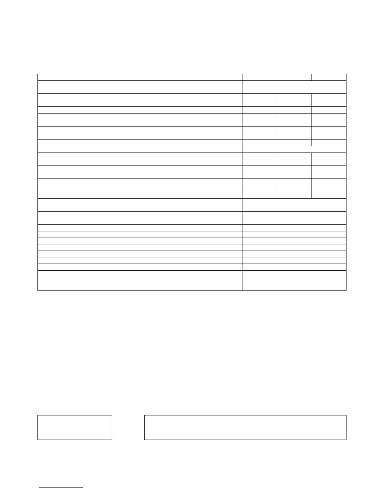
2.2 Technical data G6 400V class
Inverter size 13 14 15
Housing size C
Phases 3
Output rated power SA [kVA] 8.3 11 17
Max. rated motor power Pmot [kW] 5.5 7.5 11
Output rated current IN [A] 12 16.5 24
Max. short time current IHSR 1) [%] 180 180 150
Over current IOC 1) [%] 216 216 180
Maximum current 0Hz/corner frequency fd at fS=4 kHz If0/Ifd 1) [%] 100/180 100/180 100/180
Maximum current 0Hz/corner frequency fd at fS=8 kHz If0/Ifd 1) [%] 100/180 70/160 70/150
Maximum current 0Hz/corner frequency fd at fS=16 kHz If0/Ifd 1) [%] 60/150 – –
rated frequency fd [Hz] 6
Input rated current Iin [A] 17 23 31
Max. permissible main fuse type gG [A] 25 25 35
Rated switching frequency fSN 2) [kHz] 8 4 4
Max. switching frequency fSmax 2) [kHz] 16 8 8
Power loss at nominal operating PD 3) [W] 210 220 285
Power loss at DC supply PDdc [W] 180 180 230
Power loss standby (nOP) PDnop [W] 10 10 11
Power loss control (separated supply) PDsep [W] 2
Max. heat sink temperature THS [°C] 82
Temperature for derating the switching frequency Tdr 4) [°C] 75
temperature for uprating the switching frequency Tur 4) [°C] 70
Min. braking resistor RBmin [Ω] 39
Max. braking current IBmax [A] 21.5
Input rated voltage UN 5) [V] 400 (UL: 480)
Input voltage range Uin [V] 305…528 ±0
Input voltage range at DC supply Uindc [V] 420…746 ±0
Mains frequency FN [Hz] 50 / 60 ±2
Output voltage UA 6) [V] 3 x 0…Umains
Output frequency FA 2) [Hz] 0…400 (fs=4 kHz)
0…800 (fs=8 kHz)
minimum waiting period between two switch-on procedures [min] 5
1) The values refer percentage to the output rated current IN
2) The output frequency is to be limited in such way that 1/10 of the switching frequency is not exceeded.
3) Rated operation corresponds to UN=400 V; fSN; fA=50 Hz (typically value)
4) On reaching the temperature Tdr the switching frequency is step down. The switching frequency is increased again on cooling down to temperature
Tur.
5) At rated voltages > 460 V multiply the rated current with factor 0.86
6) The voltage at the motor is dependent on the series-connected units and on the control method (example see chapter A.1 in the annex)
The technical data are for 2/4-pole standard motors. With other pole numbers the inverter must be
dimensioned onto the motor rated current. Contact KEB for special or medium frequency motors.
The service life of the frequency inverter with intermediate voltage circuit depends on the current load
of the electrolytic capacitors in the intermediate circuit. The use of mains chokes can increase the
service life of the condensators to a considerable extent, especially when connecting to „hard“ power
systems or when under permanent drive load (continuous duty). For continuous duty (S1) drives with
a medium duty of >60%, KEB provided the use of mains chokes with a terminal voltage (Uk) of 4%.
The term "hard" power system means that the nodal point power (SNet) of the mains is very high (>>
200) compared to the output rated power of the inverter (SA).
k =
SNet 2 MVA (supply transformer)
–––– >> 200
e.g.
k = ––––––––––––––––––––– = 303 ––> Choke required
SA 6.6 kVA (12.F5)