GB - 19
Connection of the Power Unit
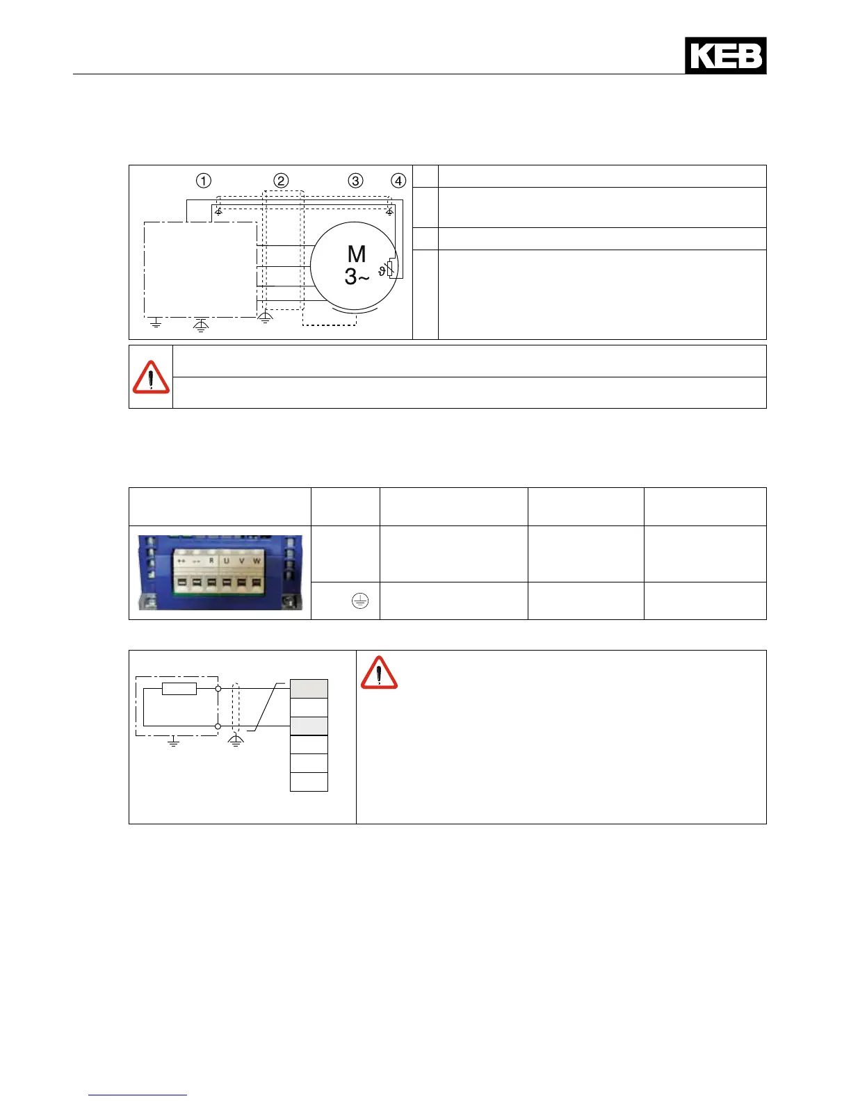
3.2.2.7 Wiring of the motor
L1
L2
L3
U
V
W
PE
U
V
W
PE
PE
T1 T2
1 KEB COMBIVERT
2 Apply motor cable, shielding on both sides
over a large surface on the function earth
3 Three-phase motor
4 Temperature monitoring (optional)
see chapter „Temperature detection"
Do not lay PTC cable of the motor (also shielded) together with control cable !
PTC cable inside the motor cable only permissible with double shielding !
3.2.3 Connection of a braking resistor
3.2.3.1 Terminal strip X1B connection braking resistor
X1B Name Function Cross-section Tightening
torque
++, R
Connection for bra-
king resistor (alter-
native ++, PB)
0.2-16 mm²
AWG 26-6
2.3 Nm
20.5 lb-inch
PE,
Connection for pro-
tective earth
Screw M4 for
ring thimble
1.3 Nm
11 lb inch
3.2.3.2 Wiring of an intrinsically safe braking resistor
X1B
R
--
++
U
V
W
R
PA
Only "intrinsically safe" braking resistors are per-
missible for this operation, since these resistors
interrupt themselves at fault such as safety fuse
without re risk. The delivered intrinsically safe
braking resistors by KEB are described in the inst-
ruction manual 00G6N1Z-0010.
3.2.3.3 Using a non-intrinsically safe braking resistor
see instruction of the brake resistors