GB - 22
Annex
Annex A
A.1 Calculation of the motor voltage
The motor voltage for dimensioning of the drive is depending on the used components. The
mains voltage reduces according to the following table:
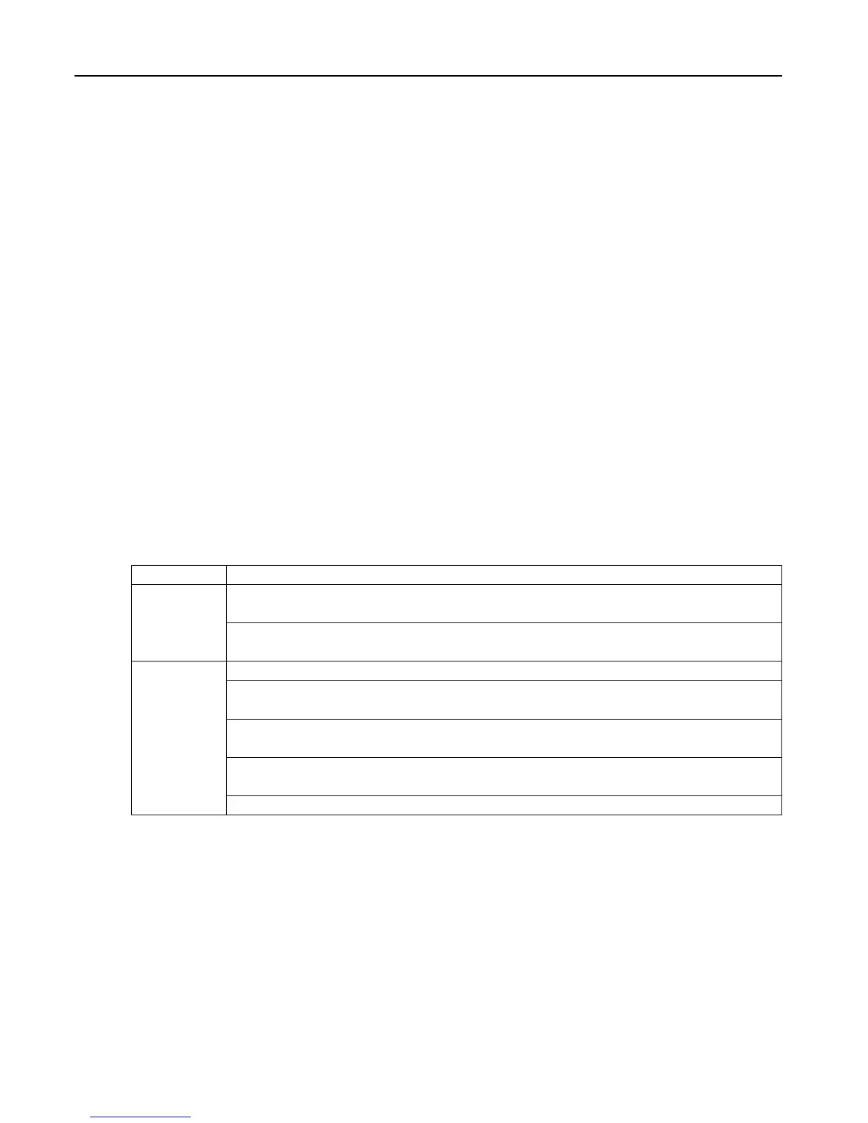
Mains choke Uk 4 % Example:
Inverter open loop 4 % Closed loop inverter with mains- and motor choke at
non-rigid supply system:
400 V mains voltage - 15 % = 340 V motor voltage
Inverter closed loop 8 %
Motor choke Uk 1 %
Non-rigid supply
system
2 %
A.2 Maintenance
All work may only be done by qualied personnel. The security must be ensured as follows:
• Disconnect power supply at MCCB
• Secure against restarting
• Await discharge time of capacitors
(if necessary controlling by measurement at „+“ and „-“, respectively at „++“ and „--“)
• Ensure loss of voltage by measurement
In order to avoid premature ageing and avoidable malfunctions, the measures mentioned
below must be carried out in the appropriate cycle.
Cycle Function
Constant
Pay attention to unusual noises of the motor (e.g. vibrations) as well as of the
frequency inverter (e.g. fan).
Pay attention to unusual smells of the motor or frequency inverter (e.g. evapo-
ration of capacitor electrolyte, braise of the motor winding).
Monthly
Check unit for loose screws and plugs and if necessary tighten up.
Clean frequency inverter from dirt and dust deposits. Pay attention especially
to cooling ns and protective grid of the fans.
Examine and clean extracted air lter and cooling air lter of the control cabi-
net.
Examine function of the fans of the KEB COMBIVERT. The fan must be repla-
ced in case of audible vibrations or squeak.
Make a visual leak test of the cooling circuit for water-cooled inverters.