40 Quick Results Guide
Pulse mode (Model 2430 only)
While in the Pulse Mode, the Model 2430 can output one or more pulses. It can output cur-
rent pulses up to 10.5A at 105V, or voltage pulses up to 105V at 10.5A. For details on Pulse
Mode operation, see the 2400 Series SourceMeter User’s Manual, Section 5.
Pulse characteristics
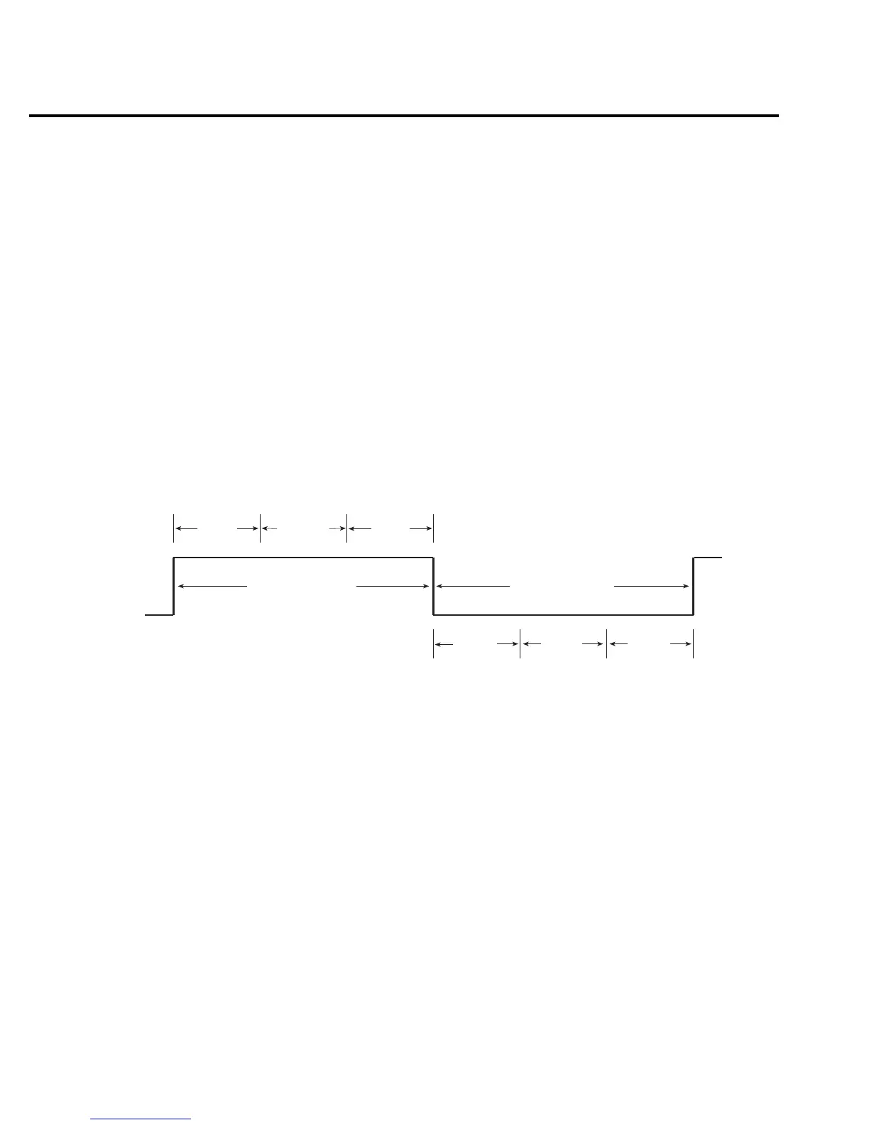
Figure 10 shows a typical pulse period. It consists of an output on-time (pulse width) and an
output off-time.
NOTE For the following discussion on pulse characteristics, it is important to understand
that a typical measured reading consists of three measurement conversions. The sig-
nal (pulse) is measured, a precise internal reference is measured and finally, zero
(common) is measured. The reading is calculated from these measurements.
Pulse width — The setting range for pulse width is from 150µsec to 5msec. Note however,
that the minimum pulse width that can be achieved in Figure 10 is determined by the minimum
pulse width overhead (80µsec), and the time it takes to measure the signal. For example if the
measure speed is set to 0.1 PLC, it will take 1.667msec to measure the signal (0.1/60Hz).
Therefore, the minimum pulse width would be 1.747msec. Setting pulse width to a value less
than that is ignored.
If (for the same example) the pulse width setting exceeds 1.747msec, the difference
becomes the “Delay” portion of the output on-time. If you set pulse width to 3msec, then the
“Delay” becomes 1.253msec.
For remote operation, all measurements can be disabled. This reduces on-time overhead to
150usec (minimum).
Meas
Sig
Meas
Ref &
Zero
PD
Delay = Pulse width delay
80µsec = Minimum pulse width overhead
Meas Sig = Signal measurement
2.9ms = Minimum output off-time overhead
Meas Ref & Zero = Reference and zero measurement
PD = Pulse delay setting
0V or 0A
Delay
Pulse Width
(Output On-Time)
Output Off-Time
2.9ms
80µsec
igure 10
ulse-measure timing

 Loading...