A-5
2611
System SourceMeter
®
2612
Multi-Channel I-V Test Solutions
METER SPECIFICATIONS
VOLTAGE MEASUREMENT ACCURACY
1, 7
TEMPERATURE COEFFICIENT (0°–18°C & 28°–50°C): ±(0.15 × accuracy specification)/°C.
CURRENT MEASUREMENT ACCURACY
6, 7
TEMPERATURE COEFFICIENT (0°–18°C & 28°–50°C): ±(0.15 × accuracy specification)/°C.
CONTACT CHECK
4
ADDITIONAL METER SPECIFICATIONS
LOAD IMPEDANCE: Stable into 10,000pF typical.
COMMON MODE VOLTAGE: 250VDC.
COMMON MODE ISOLATION: >1GΩ, <4500pF.
OVERRANGE: 101% of source range, 102% of measure range.
MAXIMUM SENSE LEAD RESISTANCE: 1kΩ for rated accuracy.
SENSE INPUT IMPEDANCE: >10GΩ.
NOTES
1. Add 50µV to source accuracy specifications per volt of HI lead drop.
2. Four-wire remote sense only.
3. Applies when in single channel display mode.
4. Includes measurement of SENSE HI to HI and SENSE LO to LO contact resistances.
5. 10A range accessible only in pulse mode.
6. De-rate accuracy by Vout/2E11 per °C when operating between 18°–28°C. Derate accuracy by Vout/2E11 + (0.15 *
Vout/2E11) per °C when operating <18°C and >28°C.
7. De-rate accuracy specifications for NPLC setting <1 by increasing error term. Add appropriate % of range term using
table below:
NPLC 200mV 2V–200V 100nA 1µA–100mA 1A–1.5A
Setting Range Ranges Range Ranges Ranges
0.1 0.01% 0.01% 0.01% 0.01% 0.01%
0.01 0.08% 0.07% 0.1 % 0.05% 0.05%
0.001 0.8 % 0.6 % 1 % 0.5 % 1.1 %
SPEED
MAXIMUM MEASUREMENT
TIME TO MEMORY
FOR 60Hz (50Hz)
4
ACCURACY (1 Year)
23°C ±5°C
±(%rdg. + ohms)
FAST 1 (1.2) ms 5% + 10
MEDIUM 4 (5) ms 5% + 1
SLOW 36 (42) ms 5% + 0.3
RANGE
DISPLAY
RESOLUTION
3
VOLTAGE
BURDEN
2
ACCURACY (1 Year)
23°C ±5°C
±(% rdg. + amps)
100.000 nA 1 pA <1 mV 0.05 % + 100 pA
1.00000 µA 10 pA <1 mV 0.025% + 500 pA
10.0000 µA 100 pA <1 mV 0.025% + 1.5 nA
100.000 µA 1 nA <1 mV 0.02 % + 25 nA
1.00000 mA 10 nA <1 mV 0.02 % + 200 nA
10.0000 mA 100 nA <1 mV 0.02 % + 2.5 µA
100.000 mA 1 µA <1 mV 0.02 % + 20 µA
1.00000 A 10 µA <1 mV 0.03 % + 1.5 mA
1.50000 A 10 µA <1 mV 0.05 % + 3.5 mA
10.0000 A
5
100 µA <1 mV 0.4 % + 25 mA
RANGE
DISPLAY
RESOLUTION
3
INPUT
RESISTANCE
ACCURACY (1 Year)
23°C ±5°C
±(% rdg. + volts)
200.000 mV 1µV
>10 GΩ
0.015% + 225 µV
2.00000 V 10 µV
>10 GΩ
0.02 % + 350 µV
20.0000 V 100 µV
>10 GΩ
0.015% + 5 mV
200.000 V 1mV
>10 GΩ
0.015% + 50 mV
SOURCE SPECIFICATIONS (continued)
PULSE SPECIFICATIONS (continued)
NOTES
1. Add 50µV to source accuracy specifications per volt of HI lead drop.
2. Full power source operation regardless of load to 30°C ambient. Above 30°C and/or power sink operation, refer to
Section 8 – Operating Boundaries in the Series 2600 Reference Manual for additional power derating information.
3. For sink mode operation (quadrants II and IV), add 12% of limit range and ±0.02% of limit setting to correspon-
ding current limit accuracy specifications. For 1A range add an additional 40mA of uncertainty.
4. For sink mode operation (quadrants II and IV), add 10% of compliance range and ±0.02% of limit setting to corre-
sponding voltage source specification. For 200mV range add an additional 120mV of uncertainty.
5. 10A range accessible only in pulse mode.
6. Accuracy specifications do not include connector leakage. Derate accuracy by Vout/2E11 per °C when operating
between 18°–28°C. Derate accuracy by Vout/2E11 + (0.15 * Vout/2E11) per °C when operating <18°C and >28°C.
7. 150mV under pulse conditions with compliance set to 1A.
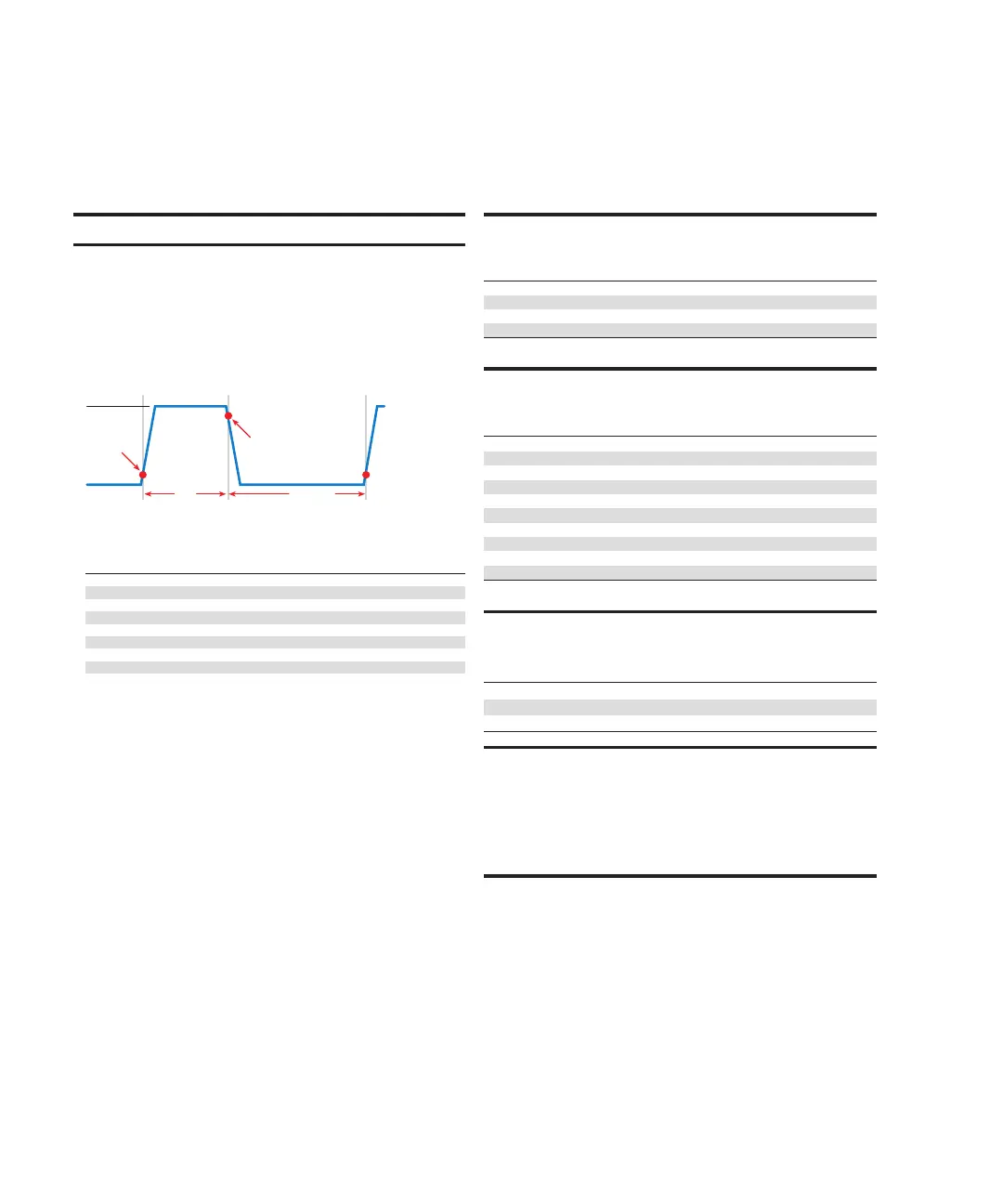
8. Times measured from the start of pulse to the start of off-time; see figure below.
9. Thermally limited in sink mode (quadrants 2 and 4) and ambient temperatures above 30°C. See power equations
in the reference manual for more information.
10. Voltage source operation with 1.5A current limit.
11. Typical performance for minimum settled pulse widths:
Typical tests were performed using remote operation, 4W sense, Keithley 2600-BAN cables and best, fixed measure-
ment range. For more information on pulse scripts, see the Series 2600 Reference Manual.
Source Value Load
Source Settling
(% of range) Min. Pulse Width
5 V
0.5 Ω
1% 300 µs
20 V
200 Ω
0.2% 200 µs
180 V
180 Ω
0.2% 5ms
200V (1.5A limit)
200 Ω
0.2% 1.5 ms
100 mA
200 Ω
1% 200 µs
1 A
20 Ω
1% 500 µs
1 A
180 Ω
0.2% 5ms
10 A
0.5 Ω
0.5% 300 µs
Pulse Level
Bias Level
Start t
on
Start t
off
90%
10%
t
on
t
off
10%