Do you have a question about the Kelly KEB Series and is the answer not in the manual?
Introduces the Kelly ebike brushless DC motor controllers' features, installation, and maintenance. Read carefully before use.
Details fault detection, voltage monitoring, current control, temperature protection, and input/output configurations.
Highlights design aspects like microprocessor intelligence, synchronous rectification, electronic reversing, and rugged construction.
Lists technical parameters such as frequency of operation, standby current, sensor supply, and operating voltage range.
Explains the naming conventions for Kelly KEB motor controller models, breaking down component identification.
Provides guidelines for physically mounting the controller to ensure proper heat dissipation and protection from contaminants.
Covers the electrical connections required for the controller, including front panel interfaces and J2 pin definitions.
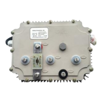
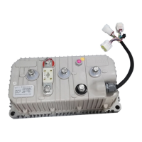
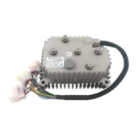
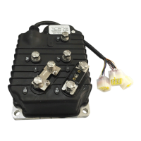
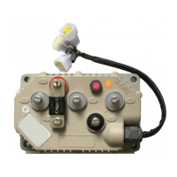
Details the physical connection points on the front panel, including metal bars and a 14-pin connector.
Lists the function of each pin within the J2 connector, crucial for system integration.
Illustrates the standard wiring diagram for the KEB controller, showing connections to motor, battery, and controls.
Explains the RS232 port functionality for computer communication, calibration, and configuration.
Outlines essential checkout procedures to be completed before operating the vehicle, ensuring correct installation.
Recommends periodic external cleaning procedures, including power disconnection and capacitor discharge.
Details how to configure the controller using a host computer via RS232 or USB port and software.
The Kelly KEB Brushless Motor Controller is a programmable device designed for efficient, smooth, and quiet control of electric bicycles, motorcycles, and scooters. It is capable of outputting high starting current while strictly limiting battery current, allowing for good acceleration and hill climbing even with relatively small batteries. The controller utilizes high-power MOSFETs and Pulse Width Modulation (PWM) to achieve efficiencies of up to 99%. A powerful microprocessor provides comprehensive and precise control, enabling users to adjust parameters, conduct tests, and quickly obtain diagnostic information.
The controller offers extended fault detection and protection, with LED flashing codes indicating fault sources. It monitors battery voltage, stopping operation if the voltage is too high and cutting back or stopping if it's too low. Built-in current loop and overcurrent protection are standard. It includes motor temperature input and protection with a configurable range, and cuts back current at low (starting around 0°C) and high (ramping down at 90°C, shutting down at 100°C) temperatures to protect both the battery and the controller. During regeneration, the controller monitors voltage and will cut back or stop regen if the voltage becomes too high. The maximum reverse speed can be configured to half of the maximum forward speed.
The KEB controller is configurable and programmable via RS-232, with software upgradeability and a Windows GUI provided. It supplies 5V power for Hall sensors and other sensors. It features three switch inputs (defaulting to throttle, brake, and reversing switches, activated by closing to ground) and three 0-5V analog inputs (defaulting to throttle, brake, and motor temperature inputs). A configurable boost switch allows the output to reach maximum current when enabled and turned on. A configurable turbo switch limits max power to half when enabled and turned on. Max reverse power can also be configured to half.
Enhanced regen brake function includes a novel ABS technique for powerful and smooth regeneration. A configurable 12V brake signal input can be used instead of a motor temperature sensor. Optional joystick throttle allows for a single 0-5V signal for both forwarding and reversing. Thermal overload detection and protection safeguard the motor from over-temperature, designed using Silicon temperature sensors KTY83-122. It has three Hall position sensor inputs (open collector, pull-up provided) and an optional supply voltage range of 8V-30V.
The controller is specially designed for electric bicycles and scooters, featuring intelligence with a powerful microprocessor. It uses synchronous rectification, ultra-low drop, and fast PWM for very high efficiency. Electronic reversing is supported. It monitors voltage on three motor phases, bus, and power supply, as well as 12V and 5V voltage sources. Current is sensed on all three motor phases, with a current control loop and hardware overcurrent protection. Hardware overvoltage protection is also included.
The KEB controller supports torque mode, speed mode, and balanced mode operation. It has configurable limits for motor current and battery current, with battery current limiting that doesn't affect takeoff performance. It allows for more startup current and speed. The design ensures low EMC and provides LED fault codes for diagnostics. Battery protection includes current cutback, warning, and shutdown at configurable high and low battery voltages.
The controller supports motors with any number of poles and configurable 60-degree or 120-degree Hall position sensors. A brake switch is used to initiate regeneration, and a 0-5V brake signal commands regen current. Three modes of regenerative braking are supported: brake switch regen, release throttle regen, and 0-5V analog signal variable regen. High pedal protection can disable operation if power is applied with high throttle. Current multiplication allows the controller to draw less current from the battery while outputting more current to the motor. Installation is easy, with a 3-wire potentiometer working effectively. It provides current meter output and can be programmed using a standard PC/Laptop computer with user-friendly software provided at no cost.
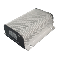
The controller is housed in a rugged aluminum casing for maximum heat dissipation and harsh environment protection. It features rugged high current terminals and aviation connectors for small signals. Thermal protection includes current cutback, warning, and shutdown at high temperatures.
There are no user-serviceable parts inside the controllers, and opening the controller is not recommended as it may cause damage. However, periodic cleaning of the controller's exterior is necessary. When working with any battery-powered vehicle, proper safety precautions must be taken, including training, eye protection, avoiding loose clothing and jewelry, and using insulated tools.
Minor maintenance includes removing power by disconnecting the battery, discharging capacitors by connecting a load (e.g., contactor coil or horn) across the B+ and B- terminals, and removing any dirt or corrosion from the bus bar area by wiping with a moist rag (ensuring it's dry before reconnecting the battery). Connections to the bus bars should be kept tight, using two insulated wrenches to avoid stressing the bus bars.
The controller can be configured using a host computer via RS232 or USB. A straight RS232 cable or Kelly Standard USB to RS232 Converter connects the 9-pin connector on the face panel to the computer. The controller requires 18V to 90V supplied to PWR, with the power supply ground wired to any RTN pin. It's important not to connect B+, throttle, etc., during configuration. Configuration software is regularly updated and should be uninstalled and reinstalled with the latest version from the Kelly Controls website. It is crucial not to connect the configuration software when the motor is running.
| Brand | Kelly |
|---|---|
| Model | KEB Series |
| Category | Controller |
| Language | English |