Kelly Ebike Brushless DC Motor Controller User’s Manual V 3.3
3.2 Connections
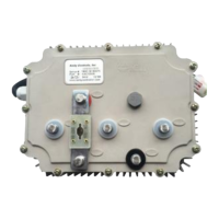
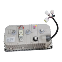
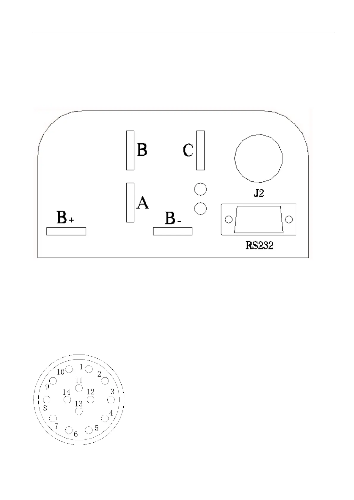
3.2.1 Front Panel of KEB Motor Controller:
Five metal bars and a 14pin rugged connector are provided for connecting to the battery,
motor and control signals in the front of the controller shown as Figure 2.
Figure 2: Front panel of KEB motor controller
B+: battery positive
B-: battery negative
A: Output U/1/A phase
B: Output V/2/B phase
C: Output W/3/C phase
Figure 3: The connecting diagram of J2
J2 Pin Definition
1- PWR: Controller power supply
2- RTN: Signal return, or power supply ground
3- RTN: Signal return
4- 12V high-level brake and motor temperature input
5- Throttle analog input, 0-5V
6- Brake analog input, 0-5V
7- 5V: 5V supply output, <40mA
8- Micro_SW: Throttle switch input.
 Loading...