KEMPOWELD 4200, 4200W, 5500W / 0531 – 5
© KEMPPI OY
S1, H1
H2
S2
S3
X1
05
X2
Sw1
F2
S4
Hw4
Hw3
MSD-1
02
03
01
X3
Sw2
F1
X4
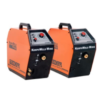
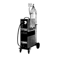
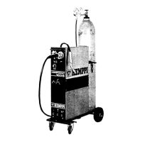
1.4. KEMPOWELD PANELS
1.4.1. Operation control and connectors
S1 Main switch (voltage range)
S2 Voltage selecting switch (coarse grading)
S3 Voltage selecting switch (fine grading)
H1 Pilot lamp for main switch
H2 Pilot lamp for overheating (power source)
X1 Return current connector (coarser arc)
X2 Return current connector (softer arc)
05 Accessory drawer
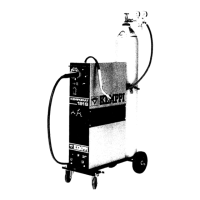
MSD-1 V/A metering unit
(accessory for 4200 and 4200W)
MSD-1 V/A metering unit
(included in delivery of 5500W)
1.4.2. Parts of cooling unit Kempoweld
4200W and 5500W
S4 Main switch of cooling unit
Sw1 Selecting switch for gun´s cooling mode
Sw2 Water cooling test switch
Hw4 Pilot lamp for overheating
Hw3 Pilot lamp for lacking water pressure
F2 Fuse for cooling unit (2 A delayed / 4200W)
F2 Fuse for cooling unit (4 A delayed / 5500W)
02 Water circulation return connector
03 Water circulation output connector
04 Filler hole for water tank
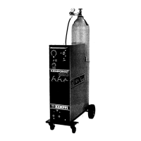
1.4.3. Rear plate of Kempoweld 4200,
4200W and 5500W
01 Inlet of mains cable
F1 Fuse of auxiliary transformer (8 A delayed)
X3 Welding current connector for wire feeder
unit (+ pole)
X4 Control connector for wire feeder unit
 Loading...