8 – KEMPOWELD 4200, 4200W, 5500W / 0531 © KEMPPI OY
05
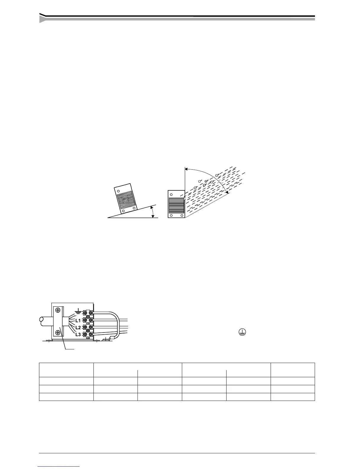
max
15º
2. INSTALLATION
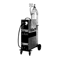
2.1. TRANSPORT AND LIFTING OF THE MACHINE
On the power source bottom there are four fixed lifting points for lifting devices, hole diameter 47 mm. On the
power source´s front panel and above the wire feeder unit there are handles designed for moving the units on the
floor.
Lift the entire power source only from lifting points on the bottom! You may move the units from handles only by
hands, it is forbidden to use any mechanical devices!
Ensure that the unit is kept during lifting between lifting linens. When necessary use additional binding round
the lifting linens and the unit´s upper part. Use the protection between the lifting device and the unit in order to
eliminate impacts and shocks.
2.2. SITING THE MACHINE
Site the machine on a stationary, horizontal, dry and clean base from which there does not come any dust etc. into
inlet air through the rear grate.
Ensure the free circulation of the cooling air.
Degree of protection IP23C of the machine allows at its maximum the water jet coming in 60° angle to hit machine´s
outer covering. See to that the machine is positioned away from the line of the particle spray, created by grinding
tools etc.
Mounting of the mains cable
The cable is entered into the machine through the inlet ring on the rear
wall of the machine and locked with a cable clamp (05).
The phase conductors of the cable are coupled to connectors L1, L2 and
L3. The earth protection coloured green-yellow is coupled to connector
marked with earth protection symbol . If you are using 5-conduc-
tor cable, you must cut the zero conductor to the level of the cable´s
protective shield.
Sizes of mains cables and fuse ratings for the machine at 100% ED duty cycle are specified in the table below:
2.4. WELDING AND RETURN CURRENT CABLES
Use only copper cables with cross-sectional area of at least 50 mm
2
. In enclosed table are shown typical loading
capacities of rubber insulated copper cables, when ambient temperature is 25 °C and conductor temperature is
85 °C.
In cables of S type there is protective grounding conductor coloured green-yellow.
Kempoweld 4200 4200W 5500W
Rated voltage 230 V 400 V 230 V 400 V 400 V
Voltage range 220...240 V 380...415 V 220 V...240 V 380 V...415 V 380...415 V
Fuses, delayed 25 A 16 A 25 A 16 A 32 A
Connection cable 4 x 6.0 S mm² 4 x 2.5 S mm² 4 x 6.0 S mm² 4 x 2.5 S mm² 4 x 6.0 S mm²
– See to that in front of the machine as well as at the rear of the machine there is at least 20 cm free distance to
allow good circulation of the cooling air through the machine.
– Protect the machine against heavy rain and in circumstances over 25°C against direct sunshine
2.3. CONNECTION TO THE MAINS SUPPLY
Connection and change of the mains cable and the plug must be carried out only by a competent electrician.
Remove for the mounting of the mains cable the left side plate, seen from the front of the power source.
The Kempoweld power source is equipped with 5 m supply cable without plug. The mains cable is according to the
marking H07RN-F of the norm Cenelec HD22.The mains cable must be changed if it does not meet local regula-
tions.
rain water
 Loading...