Check Operation
Refer to the Use and Care Guide packaged with the
range for operating instructions and for care and
cleaning of your range.
Remove all packaging from the oven before testing.
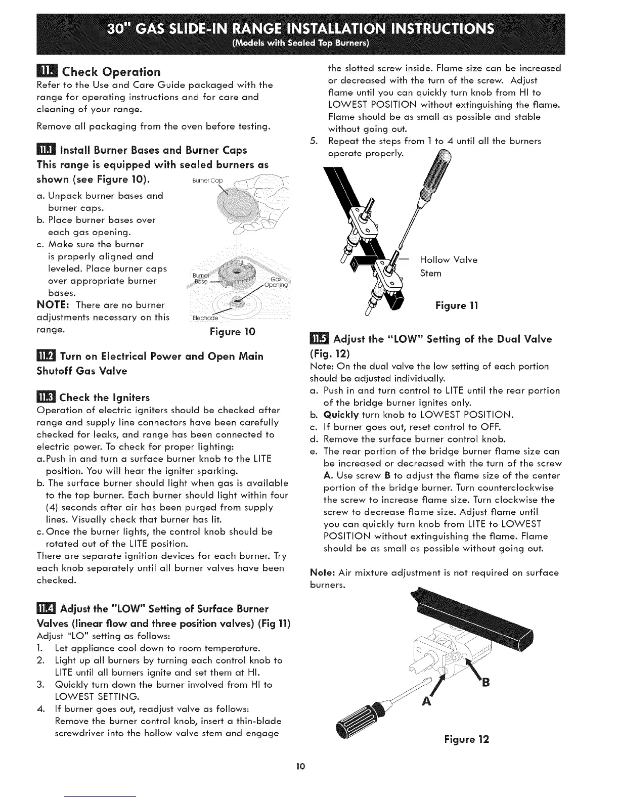
Install Burner Bases and Burner Caps
This range is equipped with sealed burners as
shown (see Figure 10).
a. Unpack burner bases and
burner caps.
b. Place burner bases over
each gas opening.
c. Make sure the burner
is properly aligned and
leveled. Place burner caps
over appropriate burner
bases.
NOTE: There are no burner
adjustments necessary on this
range.
Electrode
Figure 10
Turn on Electrical Power and Open Main
Shutoff Gas Valve
Check the igniters
Operation of electric igniters should be checked after
range and supply line connectors have been carefully
checked for leaks, and range has been connected to
electric power. To check for proper lighting:
a.Push in and turn a surface burner knob to the LITE
position. You will hear the igniter sparking.
b. The surface burner should light when gas is available
to the top burner. Each burner should light within four
(4) seconds after air has been purged from supply
lines. Visually check that burner has lit.
c. Once the burner lights, the control knob should be
rotated out of the LITE position.
There are separate ignition devices for each burner. Try
each knob separately until all burner valves have been
checked.
.
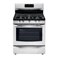
the slotted screw inside. Flame size can be increased
or decreased with the turn of the screw. Adjust
flame until you can quickly turn knob from HI to
LOWEST POSITION without extinguishing the flame.
Flame should be as small as possible and stable
without going out.
Repeat the steps from I to 4 until aii the burners
operate properi .
Hollow Valve
Stem
Figure 11
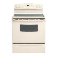
Adjust the "LOW" Setting of the Dual Valve
(Fig.12)
Note: On the dual valve the low setting of each portion
should be adjusted individually.
a. Push in and turn control to LITE until the rear portion
of the bridge burner ignites only.
b. Qulckly turn knob to LOWEST POSITION.
c. If burner goes out, reset control to OFF.
d. Remove the surface burner control knob.
e. The rear portion of the bridge burner flame size can
be increased or decreased with the turn of the screw
A. Use screw B to adjust the flame size of the center
portion of the bridge burner. Turn counterclockwise
the screw to increase flame size. Turn clockwise the
screw to decrease flame size. Adjust flame until
you can quickly turn knob from LITE to LOWEST
POSITION without extinguishing the flame. Flame
should be as small as possible without going out.
Note: Air mixture adjustment is not required on surface
burners.
Adjust the "LOW" Setting of Surface Burner
Valves (linear flaw and three position valves) (Fig 11)
Adjust "LO" setting as follows:
1. Let appliance cool down to room temperature.
2. Light up all burners by turning each control knob to
LITE until all burners ignite and set them at HI.
3. Quickly turn down the burner involved from HI to
LOWEST SETTING.
4. If burner goes out, readjust valve as follows:
Remove the burner control knob, insert a thin-blade
screwdriver into the hollow valve stem and engage
: \}
Figure 12
lo