19
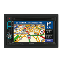
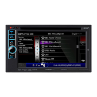
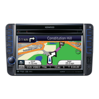
DNX4280BT/5180/5280BT/5380/5380M
/5380BT/5580BT/6040EX/6180/6480BT/6980
Key Specifi cation
Init : Select the item to initialize. (selection will be can-
celled by pressing it again)
■
Start : Initialize the information of the item selected by
pressing [Init] key.
Disp : Display switching of the disc play back time.
DVD-Video
→
CD
→
VCD
→
Media Disc
→
DVD Video
→
· · ·
Serial : Transfer to the Serial No. Writing-in screen.
Tuner Mute Level
: Transfer to Tuner Mute Level Adjustment screen.
DVS8700 Adjust
: Transfer to DVS8700 Adjustment screen.
DivX Registration Code Clear
: Clear DivX Registration Code.
Note:
Eject the disc before performing this operation.
DC Offset Clear
: Clear the DC Offset information stored in the non-
volatile memory.
Return : Transfer to Test Mode Main screen.
2.2.3.1 DivX Registration Code
Since the Registration Code cannot be displayed constantly
after the model is made to be compatible with Ver3.0, the
following status of the DivX is displayed instead.
• Activate
• Deactivate
• None (In factory default condition or when the code is
cleared)
Hide this item for the models with “
°
” listed in the DivX col-
umn of Table 1.2.1.
2.2.3.2 DC Offset
Display DC Offset detection information (for details of dis-
play, refer to the Table 2.2.3.2).
Details of display DC Offset detection status
None DC Offset not detected
Detect (x)
DC Offset detected (x = 0 to 3: Number of
capacitor leak detection)
Table 2.2.3.2 Display regarding DC Offset
2.2.3.3 Service Information
Power ON time, Disc play back time, Monitor Open count,
and Disc Eject count are displayed.
Display fi xed characters “Monitor mecha don’t exist” in the
number of Monitor Open for the models with “
°
” listed in
the Panel mechanism column of Table 1.2.1.
2.2.3.4 Power on log
Display if the unit was powered on or not.
Details of display are as following.
Power Detected: Has power on log.
No Detection: Does not have power on log.
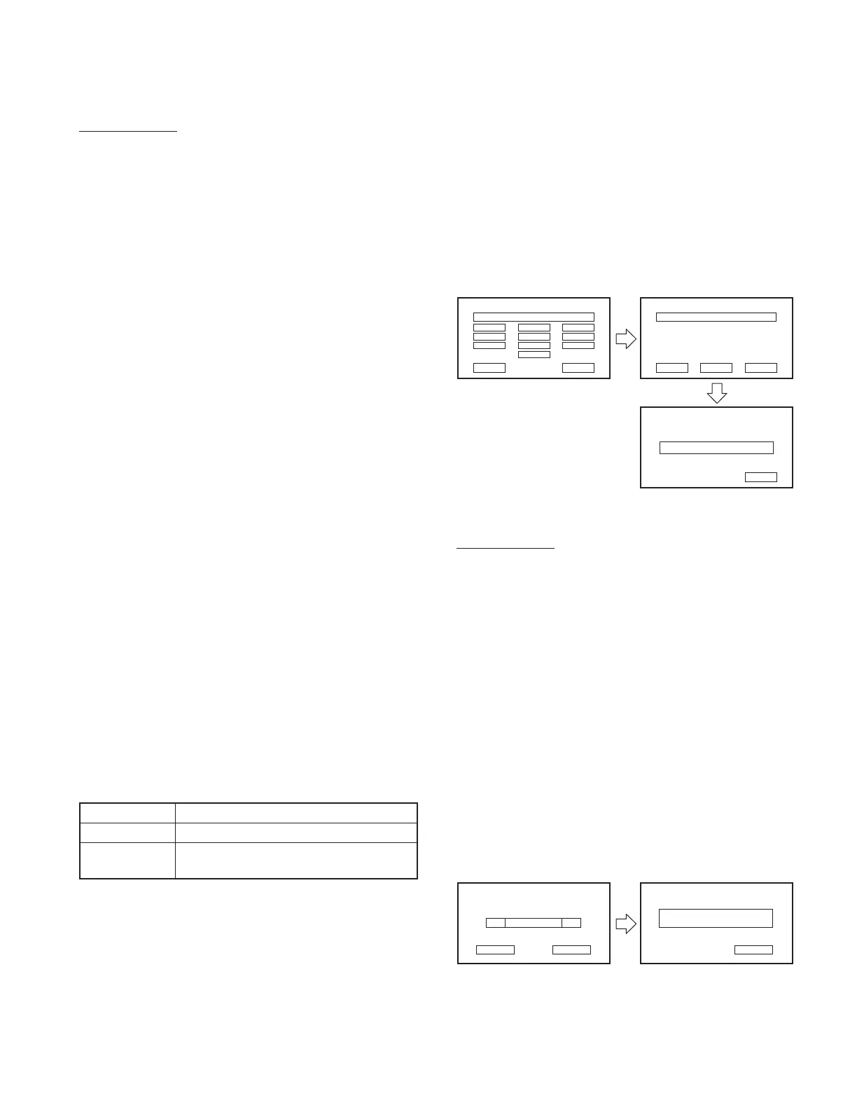
2.2.3.5 Serial No. Entry screen
Enter the serial number of each set from this screen.
The Serial No. Entry screen is shown in Figure 2.2.3.5.
Write OK/NG
1
4
7
Clear Cancel
2
5
8
3
6
9
0
Serial Number Input
– – – – – – – –
Clear Enter Cancel
Serial Number Input
X X X X X X X X
Serial Number Input
Return
Figure 2.2.3.5 Serial No. Entry screen
Key Specifi cation
0~9 : 10key used to enter the serial number.
Clear : Clear the serial number being input.
Cancel : Transfer to Service screen.
Enter : Start entering the serial number.
Return : Transfer to Service screen.
∗
Background color will be blue when “Write OK” is dis-
played.
∗
Background color will be red when “Write NG” is dis-
played.
∗
When “Write NG” is displayed after pressing the [Enter]
key, enter the Test mode again to start from the beginning.
2.2.3.6 Tuner Mute Level Adjustment screen
Perform adjustment of the Mute Level memorized in the
nonvolatile memory of Tuner F/E.
The Tuner Mute Level screen is shown in Figure 2.2.3.6.
■
Write Cancel
Tuner Mute Level Tuner Mute Level
DW
UP∗∗∗∗
Write OK/NG
Return
Figure 2.2.3.6 Tuner Mute Level Adjustment screen
TEST MODE
 Loading...