NXR-800
41
Procedure for Traceability of BGA Package and
How to Replace Control Unit
This clause is procedure when you replace Control unit
on you repair. Implement traceability of BGA package in or-
der to make sure BGA failure in prior to replace Control Unit.
You choose appropriate procedure accordingly.
1. Traceability of BGA Package ICs in Control Unit
The control unit (X53-414) of NXR-800 series have BGA
package ICs. BGA package IC is diffi cult to trace whether it
be broken. So, control unit is diffi cult to confi rm whether
it has a problem. This document shows a simple method
by PC to confirm the control unit has problem. The two
methods for traceability in BGA packages IC are provided as
below.
1-1. Simplifi ed traceability
a) Open the top cover of control unit.
b) Slide the tab on DIP_SW4 (Ref No. S700) to the ON posi-
tion. (See Fig 1.)
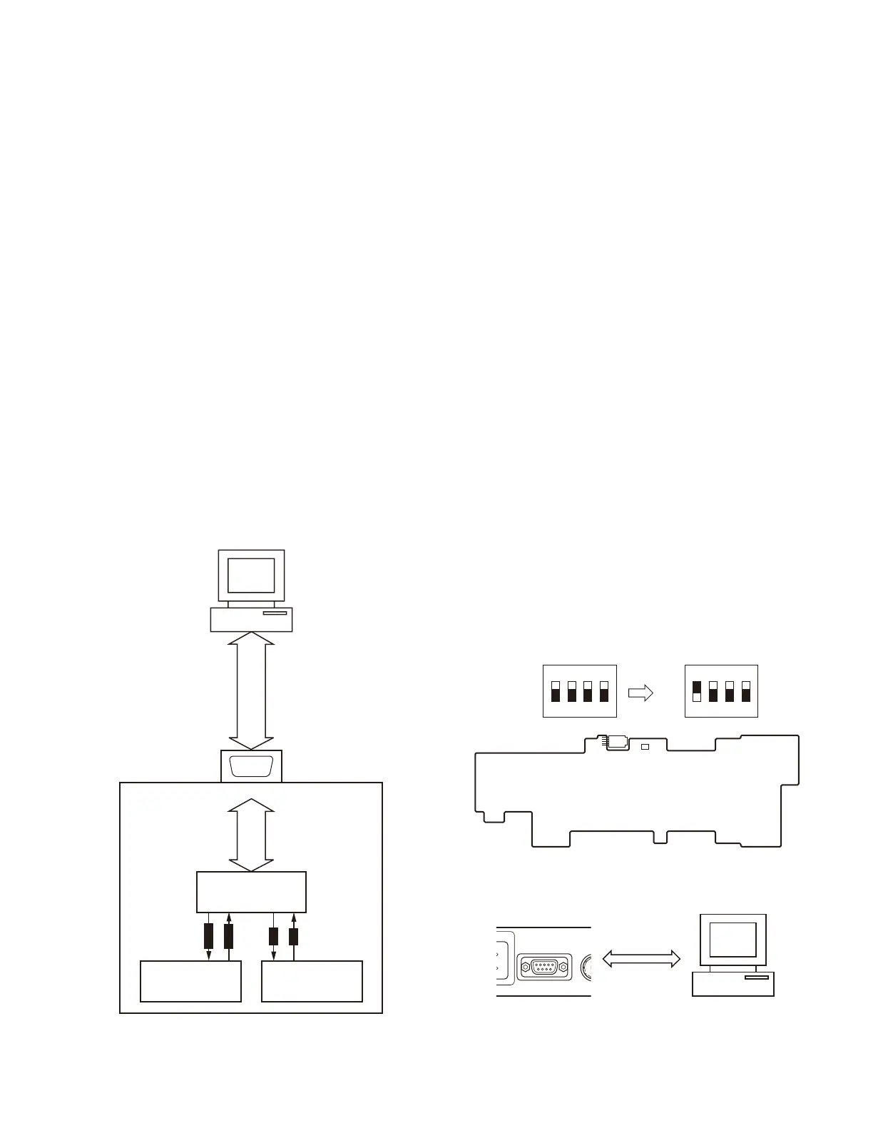
c) Connect a cross-wired RS232C cable to COM port on the
front panel of NXR-800. Plug the other end of the cable
to PC. (See Fig 2.)
d) Run a communication software, example a Hyper Termi-
nal in Windows, and set the following parameters.
e) COM port: COM port of NXR-800 used in step c.
Confi guration in communication port
Communication speed: 115200bps
Data Length: 8-bit
Parity: None
Stop bits: 1
Flow control: Hardware
f) Apply 13.8VDC to NXR-800. When BGA ICs mounted in
this control unit works correctly, the following messages
appears on the screen of communication software. If the
software doesn’t show below messages, it’s supposed
that BGA package IC is broken.
NEXEDGE IPL 1.00 *1
COPYRIGHT KENWOOD CORPORATION
2007 ALL RIGHTS RESERVED
CPU[R] Version 1.00 *2
CPU[M] Version 1.00 *3
*1: Appearing this information means the boot program
in Main MPU (IC703) is correctly working.
*2: ppearing this information means the boot program at
the RF control MPU (IC34) is correctly working.
*3: Appearing this information means the boot program
at the Modem control in MPU(IC325) is correctly
working.
Note: IPL and CPU[R], CPU[M] version will be updated by
any modifi cation or improvement in future.
g) After that slide the tab on DIP_SW4 to OFF position, be-
fore close the top cover of control unit.
TROUBLE SHOOTING
VO
COM
OFF/
T
LE
Front panel PC
A cross-wired
RS-232C cable
Control block
Main MPU: IC703
RF control
MPU: IC34
Modem control
MPU: IC325
TXD,RXD,
RTS,CTS
CD,RD,SD,DTR,
DSR,RTS,CTS,RI
COM (DSUB9)
Control unit (X53-4140-10)
Component side
DIP SW
(S700)
4321
OFF
ON
4321
OFF
ON
Default position of
DIP SW (S700)
Slide SW4 to
“ON” position
Fig. 2
Fig. 1

 Loading...