NXR-800
46
Audio AMP (IC29)
LAN_IC (IC719)
DSP_I/O (IC37)
33BU
33SHDC50
18DSP
DSP_Core (IC37)
Switch (Q302)
1.8V_AVR (IC18)
3.3V_AVR (IC329)
3.3V_AVR (IC15)
3.3V_AVR (IC6)
DC/DC converter
(IC11, Q3)
Main MPU I/O (IC703)
Audio_circuit
LED, Option
RF_Control_MPU I/O (IC34)
RF_Control_MPU I/O (IC34)
Rechargeable battery (BA300)
SRAM (IC700), RTC (IC701)
Main MPU_Core (IC703)
Modem Control MPU (IC325)
TX_Vocoder/RX_DSP_I/O
(IC323/324)
TX_Vocoder/RX_DSP_Core
(IC323/324)
15DSP
33MPU
33AUD
15SH
1.5V_AVR (IC306)
1.5V_AVR (IC307)
Switched by
Modem Control
MPU (IC325)
50MPU
DC8
+B
5V_AVR (IC16)
DC/DC converter
(IC10, Q2)
Switched by
Modem Control
MPU (IC325)
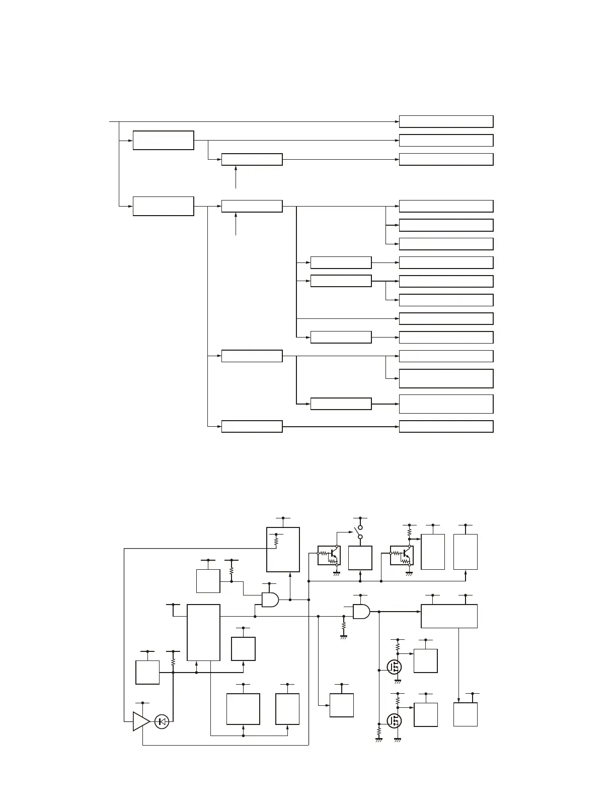
■
Initialization of the Modem control MPU (IC325)
(normal oscillation of X301 and normal reset-
unlock of IC303)
Refer to Traceability procedure for IC325.
■
Unlocking “SYS_RST” Signal on the Modem
control MPU (IC325) starts Up all Hardware
Blocks
Refer to the Reset circuit below.
33BU
33SH33SH
IC700
SRAM
IC719
LAN
IC703
Main MPU
33SH
100K
100K
100K
D16C_RST
33SH
IC708
33MPU
IC314
IC325
Modem
Control
MPU
50MPU
IC34
RF Control MPU
33SH
33SH
33MPU
IC303
33MPU
33MPU
33MPU
DSP_RST
RESET_D
IC324
TX
Vocoder
DSP
33MPU
IC323
RX
DSP
50MPU
IC35
50MPU
WP
ADSP_RST
IC37
DSP
33SH
IC17
50MPU
EEPROM
each
RF unit
33SH
33SH
IC702
Flash
50MPU
33SH
from RTE
SYS_RST
47K
33MPU
50MPU
WP
■
External DC 13.8V Power Source applied to the NXR-800 Terminal
Refer to the power supply diagram sequence below.
Reset circuit
TROUBLE SHOOTING

 Loading...