TK-7160/7162
15
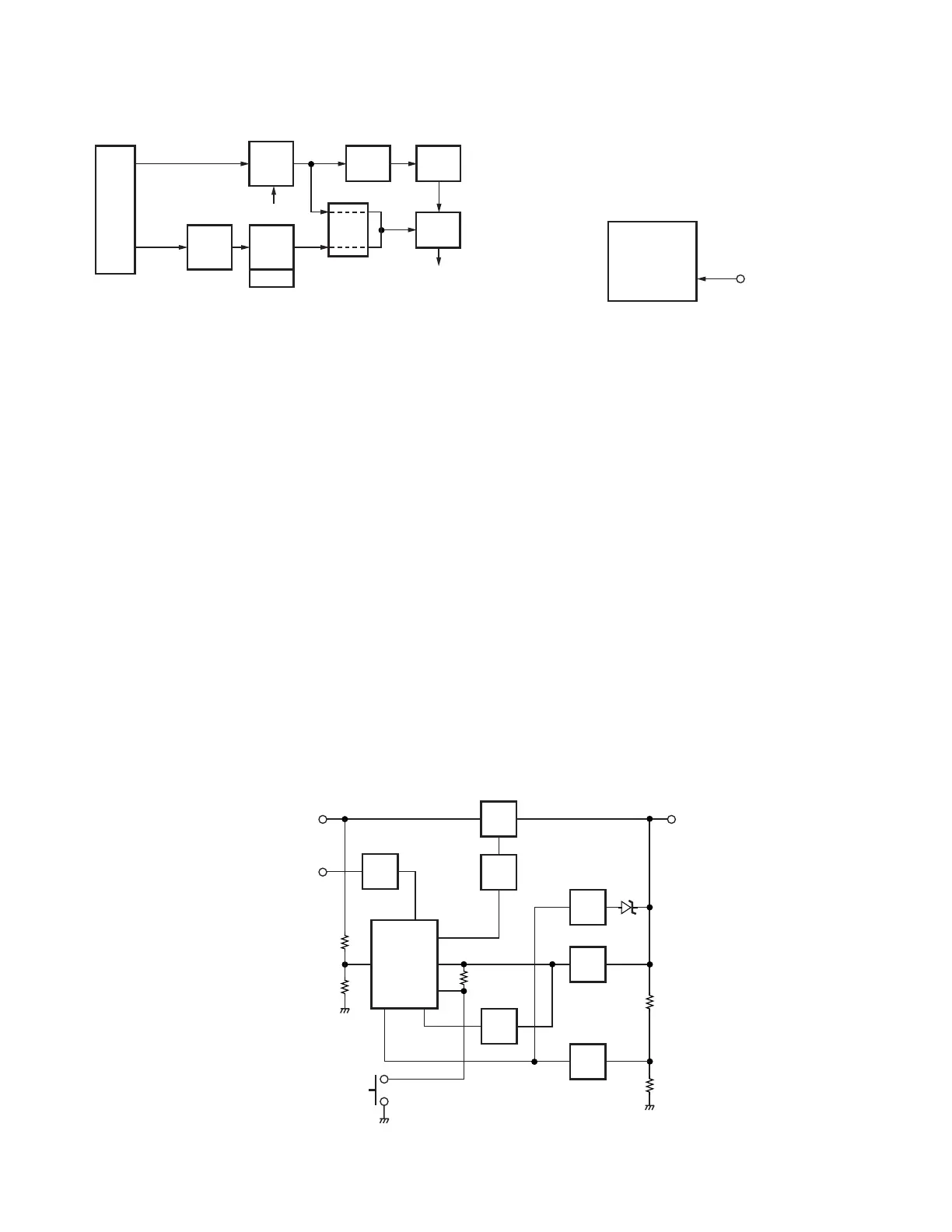
■ Decode
• Low-speed data (QT, DQT)
The demodulated signal from the FM IC (IC321) is passed
through a low-pass filter (IC211 1/2) to remove frequency of
300Hz or more.
The signal is input to pin 88 of the CPU. The CPU digitizes
this signal, performs processing such as DC restoration, and
decodes the signal.
• High-speed data (DTMF)
The DTMF input signal from the IF IC is amplified by IC241
and goes to the DTMF decoder in the IC241. The CPU then
processes the decoded information.
• High-speed data (5-tone)
The demodulated signal from the IF IC (IC321) is amplified
by IC241 and passes through a high-pass filter to remove fre-
quency of 300Hz or less. The CPU digitizes this signal and
decodes the signal.
Fig. 15 Decode
Q84
SW
Q31
SW
Q42
SW
Q81
SW
IC43
AVR
D81
B
IC44
RST
SBC
IGN
R93R92
R49R50
INT
5M
BATT
IC101
CPU
POWER
SW
POWER
RESET
5M
IC45
AVR
SB
IGN
• MSK
The MSK input signal from the IF IC goes to pin 5 of IC241.
The signal is demodulated by MSK demodulator in IC241.
The demodulated data goes to the CPU for processing.
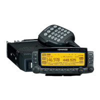
Fig. 16 Power supply circuit
CIRCUIT DESCRIPTION
X401
TCXO
IC201
D/A
VCO
IC241
AQUA
IC
IC241
AQUA
IC
IC213
SW
IC401
PLL
TCXO
MOD
VCO
MOD
HT
DI
LSDO
QT/DQT
HSDO
DTMF/
5-tone
IC101
CPU
MSK
Fig. 14 Encode
Power Supply Circuit
When the power switch on the display unit is pressed, the
power port on the display unit which is connected port 17
(POWER), goes low, then port 78 (SBC) goes high, Q42 turns
on, SB SW (Q31) turns on and power (SB) is supplied to the
radio.
When the DC power supplied to the radio, the voltage
regulator IC (IC43) supply into the CPU VDD and reset voltage
detect IC (IC44). IC44 will generate signal (RESET) in to the
reset terminal on the CPU (IC101) to carry out a power ON
reset. Also, CPU (IC101) is checking on port 91 (BATT). If DC
power is less than about 9.5V, the radio is unable to power
on.
When the DC power voltage deceases from normal volt-
age, the INT voltage detector IC (IC45) will set to high on CPU
port 18 (INT). If B line becomes less than about 9.5V, CPU
will send the backup data to EEPROM (IC81) and go into
STOP mode.
This circuit has an overvoltage protection circuit. If a DC
voltage of 16V or higher is applied to the base of Q81, this
voltage turns Q81 on and sets port 18 (INT) to low. As a
result port 78 (SBC) is low, and turns Q42 and Q31 (SB) off.