EasyManua.ls Logo

Kenwood TKR-850 Service Manual

Kenwood TKR-850
101 pages
To Next Page IconTo Next Page
Page #1 background imageLoading...
Page #1 background image
© 2004-10 PRINTED IN JAPAN
B51-8557-30
(
N
)
1219
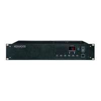
UHF FM REPEATER
TKR-850
SERVICE MANUAL
UHF FM REPEATER TKR-850
Front panel
(A62-0934-03)
Knob (DC source)
(K29-9106-04)
Key top
(K29-5460-02)
Knob (Volume)
(K29-5389-03)
Modular jack
(E08-0877-05)
Antenna cable (N)
(E30-3419-05)
Antenna cable (BNC)
(E30-3418-05)
TEST/SPKR connector assy
(E37-0913-05)
D-sub cable assy
(E37-0904-05)
DC backup terminal
(E70-0402-05)
DC cord (Ext DC in)
(E30-3414-05)
Fuse (Blade, 15A/32V)
(F05-1537-05) x 2
GENERAL ................................................................. 2
SYSTEM SET-UP ..................................................... 2
OPERATING FEATURES ......................................... 3
REALIGNMENT........................................................ 4
INSTALLATION........................................................ 5
MODIFICATION ....................................................... 8
DISASSEMBLY FOR REPAIR ................................ 10
CIRCUIT DESCRIPTION ......................................... 11
SEMICONDUCTOR DATA ..................................... 18
COMPONENTS DESCRIPTION ............................. 20
PARTS LIST............................................................ 22
EXPLODED VIEW .................................................. 34
PACKING ................................................................ 36
ADJUSTMENT ....................................................... 37
CONTENTS
TERMINAL FUNCTION ......................................... 46
INTERCONNECTION DIAGRAM........................... 50
PC BOARD
FINAL UNIT (X45-374X-XX) ............................. 52
DISPLAY UNIT (X54-3330-21) .......................... 56
TX-RX UNIT (X57-696X-XX) (A/2) ................... 60
TX-RX UNIT (X57-696X-XX) (B/2) ................... 64
RX VCO UNIT (X58-480X-XX) .......................... 68
TX VCO UNIT (X58-481X-XX) .......................... 69
SCHEMATIC DIAGRAM ........................................ 70
BLOCK DIAGRAM.................................................. 83
KES-5 (EXTERNAL SPEAKER) .............................. 86
SPECIFICATIONS................................................... 87
REVISED III
This service manual applies to products 60700001 or subsequent serial number.
In terms of the products with the serial numbers earlier than 60700001, refer to the TKR-850 service manual as per part number
B51-8557-20 and B51-8676-00.

Other manuals for Kenwood TKR-850

Question and Answer IconNeed help?

Do you have a question about the Kenwood TKR-850 and is the answer not in the manual?

Kenwood TKR-850 Specifications

General IconGeneral
BrandKenwood
ModelTKR-850
CategoryRepeater
LanguageEnglish

Summary

General and System Setup

Personal Safety Precautions

Recommended precautions for personal safety during operation and servicing.

Installation Procedures

External Power Supply Connection

Details on connecting external DC power supplies and backup batteries.

Installation and Accessories

External Speaker Connection

Instructions for connecting external speakers KES-4 or KES-5.

Accessory Cabinet Installation

Installation Details

Modifications

DC Source Switch Modification

Modification to keep the main unit powered regardless of the front panel DC source switch.

Unit Modifications

Trickle Charge for Backup Battery

Modification for trickle charging the backup battery from the external DC power supply.

Disassembly for Repair

Panel Assembly Removal

Step-by-step guide on removing the panel assembly (ABS) from the unit.

Circuit Description Overview

Receiver Circuit Details

Description of the receiver circuit, including its components and operation.

Transmitter Circuit Details

Description of the transmitter circuit, covering its various sections.

Transmitter Circuit Description

Driver and Final Power Amplifier Circuit

Details on the driver and final power amplifier circuit for transmission.

Automatic Power Control Circuit

Explanation of the Automatic Power Control (APC) circuit.

Synthesizer Circuit Description

PLL Frequency Synthesizer

Description of the Phase-Locked Loop (PLL) frequency synthesizer.

Control Circuit Description

Control Circuit Overview

Overview of the control circuit and its constituent parts.

Circuit Description Details

DSP Circuit Functionality

Description of the Digital Signal Processor (DSP) circuit for audio and signaling.

Power Supply Circuit

Description of the power supply circuit that powers various unit components.

Additional Circuit Descriptions

DC Power Supply Circuit Function

Description of the DC power supply circuit.

Semiconductor Data

Main CPU Pin Function

Pin assignments and functions for the main CPU (IC604).

Semiconductor Data Details

DSP Pin Function

Pin assignments and functions for the DSP (IC618).

Semiconductor Data and Components

Final Unit Pin Functions

Pin function details for the Final Unit (X45-374X-XX).

Component Descriptions

Final Unit Component Details

Component descriptions for the Final Unit (X45-374X-XX).

Adjustment Procedures

Power and Filter Adjustments

Procedures for adjusting maximum power, RF power levels, and BPF.

Adjustment Points and Settings

Adjustment Point Locations

Diagram indicating specific adjustment points on the PC boards.

Fine-Tuning and Alignment

Fine-Tuning the TKR-850

Guidance on fine-tuning the TKR-850 using factory-default procedures.

Alignment Procedures

Visual guides and notes for performing alignment adjustments.

Filter and Squelch Adjustments

Level and Deviation Adjustments

Deviation and Balance Adjustments

Procedures for adjusting maximum deviation, DQT balance, and QT deviation.

Signaling Deviation Adjustments

Additional Deviation Adjustments

Repeat Gain Level Adjustment

Procedure for adjusting the repeat gain level.

Adjustment and Performance Checks

Duplexer Alignment Confirmation

Procedure to confirm duplexer alignment and its effect on transmit/receive isolation.

Repeater Desensitization Confirmation

Procedure to confirm repeater desensitization by checking SINAD levels.

Interconnection Diagrams

Schematic Diagrams

Block Diagrams

Specifications (K,K2,K3 Type)

Receiver Performance Specifications

Receiver performance specifications including sensitivity and selectivity.

Transmitter Performance Specifications

Transmitter performance specifications including power output and distortion.

Specifications (E Type)

Receiver Performance (E Type)

Receiver performance specifications for the E type.

Transmitter Performance (E Type)

Transmitter performance specifications for the E type.

Related product manuals