2
TS-2000/X,TS-B2000
CONTENTS
DESCRIPTION OF COMPONENTS ......................................... 3
PARTS LIST .............................................................................. 4
ADJUSTMENT ....................................................................... 48
PC BOARD VIEWS / SCHEMATIC DIAGRAM
FILTER UNIT (X51-315X-XX) ............................................. 65
FINAL UNIT (X45-360X-XX) .............................................. 67
DISPLAY UNIT (X54-3320-00) ........................................... 79
CONTROL UNIT (X53-391X-XX) ....................................... 83
TX-RX 1 UNIT (X57-605X-XX)........................................... 97
TX-RX 2 UNIT (X57-606X-XX)......................................... 112
TX-RX 3 UNIT (X57-6070-00) .......................................... 135
SPECIFICATIONS ................................................................. 149
This serivce manual is aimed to revise and update the information on the PCBs that are used in the TS-2000(X)/TS-B2000
transceiver. Refer to the original TS-2000(X)/TS-B2000 serivce manual (B51-8558-00/B51-8569-00) for any information which
has not been covered in this manual.
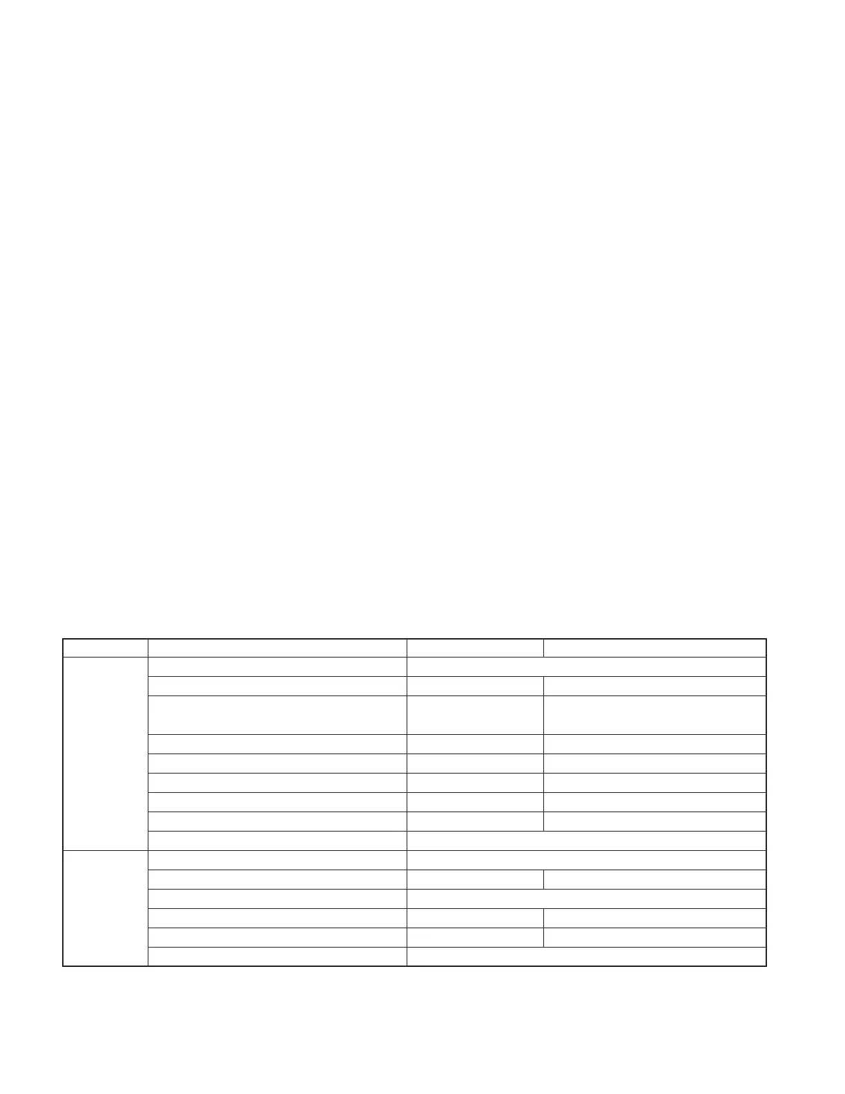
■ About PC BOARD VIEWS and SCHEMATIC DIAGRAM
This serivce manual contains the PC BOARD VIEWS and SCHEMATIC DIAGRAM for the serial numbers listed below, and
subsequent serial numbers. However, the PCB layout of the DISPLAY UNIT, TX-RX1 UNIT (C,D,E,G, and H/9) and TX-RX2 UNIT
(B,D,E,G,H,I,J, and K/11) remain unchanged from the initial lot. Also, refer to the original TS-2000(X) (B51-8558-00) or TS-B2000
(B51-8569-00) service manual for transceivers with serial numbers prior to those listed below. For the PC BOARD VIEWS and
SCHEMATIC DIAGRAM of common units, refer to the latest TS-B2000 service manual.
UNIT Name PC BOARD VIEWS SCHEMATIC DIAGRAM
Common Unit FINAL UNIT (X45-360X-XX) (A/2) S/No. 30500001~
(TS-2000(X)/ FINAL UNIT (X45-360X-XX) (B/2) S/No. 30500001~ S/No. 20900001~
TS-B2000) FILTER UNIT (X51-315X-XX) S/No. 30500001~
TS-2000 (E2), TS-B2000 (E) : S/No. 30600001~
Other models : S/No. 30500001~
CONTROL UNIT (X53-391X-XX) S/No. 30500001~ S/No. 30900001~
TX-RX1 UNIT (X57-605X-XX) (A/9) S/No. 30400141~ S/No. 31000001~
TX-RX1 UNIT (X57-605X-XX) (F/9) S/No. 30400141~ S/No. 20900001~
TX-RX2 UNIT (X57-606X-XX) (A/11) S/No. 30500001~ S/No. 30700001~
TX-RX2 UNIT (X57-606X-XX) (C/11) S/No. 30500001~ S/No. 21000001~
TX-RX2 UNIT (X57-606X-XX) (B,D,E,G,H,I,J,K/11) Initial lot (S/No. 20800001) ~
Individual Unit DISPLAY UNIT (X54-3320-00) *1 Initial lot (S/No. 20800001) ~
(TS-2000(X)/ TX-RX1 UNIT (X57-605X-XX) (B/9) *1 S/No. 30400141~ S/No. 30300001~
TS-B2000) TX-RX1 UNIT (X57-605X-XX) (C,D,E,G/9) *1 Initial lot (S/No. 20800001) ~
TX-RX1 UNIT (X57-605X-XX) (H/9) *2
Initial lot (S/No. 21000001) ~
S/No. 21100001~
TX-RX1 UNIT (X57-605X-XX) (I/9) *2 S/No. 30400141~ Initial lot (S/No. 21000001) ~
TX-RX3 UNIT (X57-6070-00) *3 S/No. 30500001~
*1 : TS-2000/X only
*2 : TS-B2000 only
*3 : TS-2000X only
 Loading...