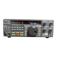
3
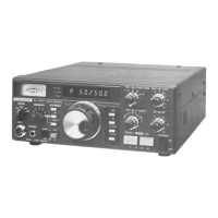
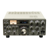
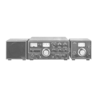
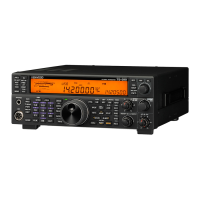
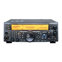
TS-2000/X,TS-B2000
FINAL UNIT (HF) (X45-360X-XX) (A/2)
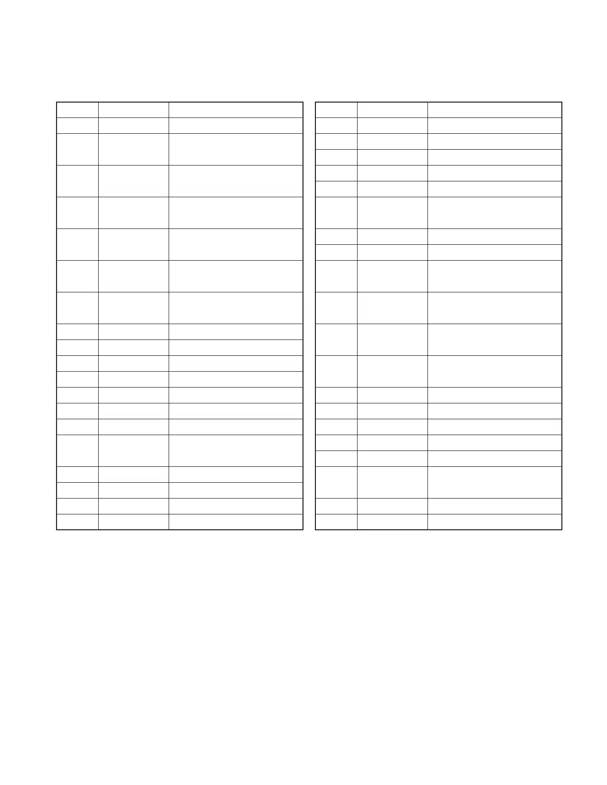
Ref. No. Use / Function Operation / Condition
Q1,2
Predrive amplifier
HF/VHF band amplifier
Q3,4 Drive amplifier HF/VHF band push-pull wide-band
amplifier
Q6,7 Final amplifier HF/50MHz band push-pull wide-
band amplifier
Q8 Bias control HF/50MHz band final stage bias
current control
Q101,102
Final amplifier VHF band push-pull wide-band
amplifier
Q103 Bias control VHF band final stage bias current
control
Q201 Switching ANT1 and ANT2 changeover relay
control
Q202 Switching AT relay control
Q203 Switching HF RX antenna relay control
Q204 Switching Fan control (high speed)
Q205 Switching Fan control (low speed)
Q206 Switching
High power supply voltage protection
Q207 Switching Power relay control (K201)
Q208~215
Switching
HF/50MHz band LPF band changeover
Q216,217
Switching VHF band TX/RX changeover relay
control
Q218 Switching Drive stage bias current control
IC201,202
AVR SB→8V
IC203 AVR SB→10V
IC204 AVR 8V→5V
Ref. No. Use / Function Operation / Condition
IC205 Extended I/O LPF control signal serial-parallel
IC801 Extended I/O
AT input C control signal serial-parallel
IC802 Extended I/O
AT output C control signal serial-parallel
IC803 Extended I/O AT coil control signal serial-parallel
D1 Switching
HF/VHF band drive input changeover
D2,3 Temperature Drive stage bias current control
compensation
D5 Switching
HF/VHF band drive stage bias changeover
D6 Surge absorption Relay (K1)
D7,8 Temperature HF/50MHz band final stage bias
compensation current control
D101 High-frequency VHF band reflected wave detection
rectification
D102 High-frequency VHF band forward wave detection
rectification
D103,104
Temperature VHF band final stage bias current
compensation control
D201 Surge absorption Power surge protection
D202 Surge absorption Fan
D203 Zener diode Over voltage detection
D204 Surge absorption Relay (K201)
D206~209
Surge absorption IC205 output line protection
D210 Reverse current VHF band TX/RX relay control line
prevention
D211 Zener diode Voltage detection
D801~824
Surge absorption Antenna tuning relay (K801~824)
DESCRIPTION OF COMPONENTS
 Loading...