GB
KERN DBS
Version 1.0 11/2012
Service Manual
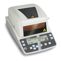
Electronic Moisture Analyser
Contents
1. Operations for Adjustment.................................................................................5
1.1 Entering the Service Mode .............................................................................................. 5
1.2 Service Menu..................................................................................................................... 6
1.3 Service Mode Functions .................................................................................................. 10
2. Disassembling and Assembling the Balance ...................................................12
2.1 Precautions ....................................................................................................................... 12
2.2 Removing the Case .......................................................................................................... 13
2.3 Replacing Components ................................................................................................... 16
2.3.1 Replacing the Thermal Fuses (S18)................................................................................... 16
2.3.2 Replacing the Main Board Assembly (B2).......................................................................... 16
2.3.3 Replacing the Analog Board Assembly (B3) ...................................................................... 17
2.3.4 Replacing the Power Board Assembly (B4) ....................................................................... 19
2.3.5 Replacing the Inlet Assembly (S11) ................................................................................... 20
2.3.6 Replacing the DBS Unit Assembly (U1) ............................................................................. 21
2.3.7 Replacing the Detector Assembly (U11) ............................................................................ 23
2.3.8 Replacing the Force Coil Assembly (L1) ............................................................................ 24
2.3.9 Replacing the Sensor shaft (U4) ........................................................................................ 27
2.3.10 Replacing the Glass Unit Assembly (S3) ........................................................................... 27
2.3.11 Replacing the Windows Panel (C7).................................................................................... 27
2.3.12 Replacing the Top Case Grille (H2) ................................................................................... 28
2.3.13 Replacing the DBS Heater (S5).......................................................................................... 29
2.3.14 Replacing the Reflector Plate (H9)..................................................................................... 29
2.3.15 Replacing the Fan Cable Assembly (C5) ........................................................................... 30
2.3.16 Replacing the LSW Cable Assembly (C6).......................................................................... 31
2.3.17 Replacing the Right Hinge (H13), Left Hinge (H14), and Hinge Springs (H15) ................. 32
2.3.18 Replacing the Thermistor (H10) ......................................................................................... 34
2.3.19 Replacing the Thermal Fuse (H6) ...................................................................................... 36
2.3.20 Replacing the level Gauge Assy (B7)................................................................................. 37
3. Cheking the Eledctronic Board..........................................................................38
3.1 Main Board Assembly (B2).............................................................................................. 38
3.2 Analog Board Assembly (B3).......................................................................................... 38
3.3 Power Board Assembly (B4) ........................................................................................... 39
4. Hardware Adjustment .........................................................................................41
4.1 Adjusting the Detector Assembly (U11) Height............................................................. 42
4.2 Adjusting the Tilt Error .................................................................................................... 43
4.3 Adjusting the Cornerload Error....................................................................................... 44
2 DBS-SH-e-1210

 Loading...