EasyManua.ls Logo

KERN DBS User Manual

KERN DBS
75 pages
To Next Page IconTo Next Page
Page #1 background imageLoading...
Page #1 background image
KERN & Sohn GmbH
Ziegelei 1
D-72336 Balingen
E-Mail: info@kern-sohn.com
Phone: +49-[0]7433- 9933-0
Fax: +49-[0]7433-9933-149
Internet: www.kern-sohn.com
Service manual
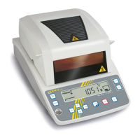
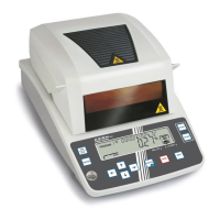
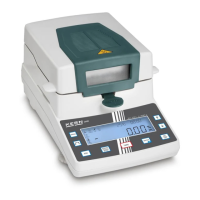
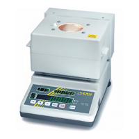
Electronic Moisture Analyzer
KERN DBS
Version 1.0
11/2012
GB
DBS-SH-e-1210

Table of Contents

Questions and Answers:

KERN DBS Specifications

General IconGeneral
CalibrationExternal
Power supply230 V / 50 Hz
TypeMoisture analyzer
Auto Power OffYes
Tare FunctionYes
ModelDBS
Readability0.001 g
Weighing range [Max]50 g/120 g/200 g
Sample temperatureUp to 200°C
DisplayLCD
Weighing plate size90 mm
Permissible ambient temperature10 °C / 40 °C
Maximum Capacity220 g
Platform Size90 mm
InterfaceRS-232

Summary

Operations for Adjustment

Disassembling and Assembling the Balance

Replacing the Thermal Fuses (S18)

Procedure for removing and installing thermal fuses (S18) in the fuse holder.

Replacing the Main Board Assembly (B2)

Steps to remove and install the main board assembly (B2), including disconnecting cables.

Replacing the Analog Board Assembly (B3)

Instructions for disconnecting cables and removing/installing the analog board assembly (B3).

Replacing the Power Board Assembly (B4)

Procedure for disconnecting cables and removing/installing the power board assembly (B4).

Replacing the Detector Assembly (U11)

Steps to unsolder sensor cables and replace the detector assembly (U11).

Replacing the Force Coil Assembly (L1)

Detailed procedure for removing and installing the force coil assembly (L1).

Replacing the Glass Unit Assembly (S3)

Instructions for loosening bolts and sliding out the glass unit assembly (S3).

Replacing the Thermistor (H10)

Procedure for removing the blind cover and pulling out the thermistor (H10).

Replacing the Thermal Fuse (H6)

Steps to remove the heater frame and replace the thermal fuse (H6).

Checking the Electronic Board

Hardware Adjustment

Adjusting the Detector Assembly (U11) Height

Procedure to adjust the detector assembly (U11) height using a multimeter and socket head bolts.

Adjusting the Tilt Error

Steps to adjust the tilt error by using shims and adjusting screws on the lever assembly.

Adjusting the Cornerload Error

Procedure for adjusting cornerload error using calibration weights and special tools.

EEPROM Operations

Performance Inspection

Troubleshooting

General Corrective Measures

Common problems and their solutions, including display issues, key malfunctions, and errors.

Nothing Is Displayed

Troubleshooting flowchart for when the display shows no output, checking power supply and fuses.

Error Display

List of error codes, their names, and descriptions for diagnosing issues.

Reproducibility of Weight Measurements Is Poor

Flowchart for diagnosing poor weight measurement reproducibility, checking installation and components.

Related product manuals