2.3.
e
l
cing the Detect
Assembl
U11)
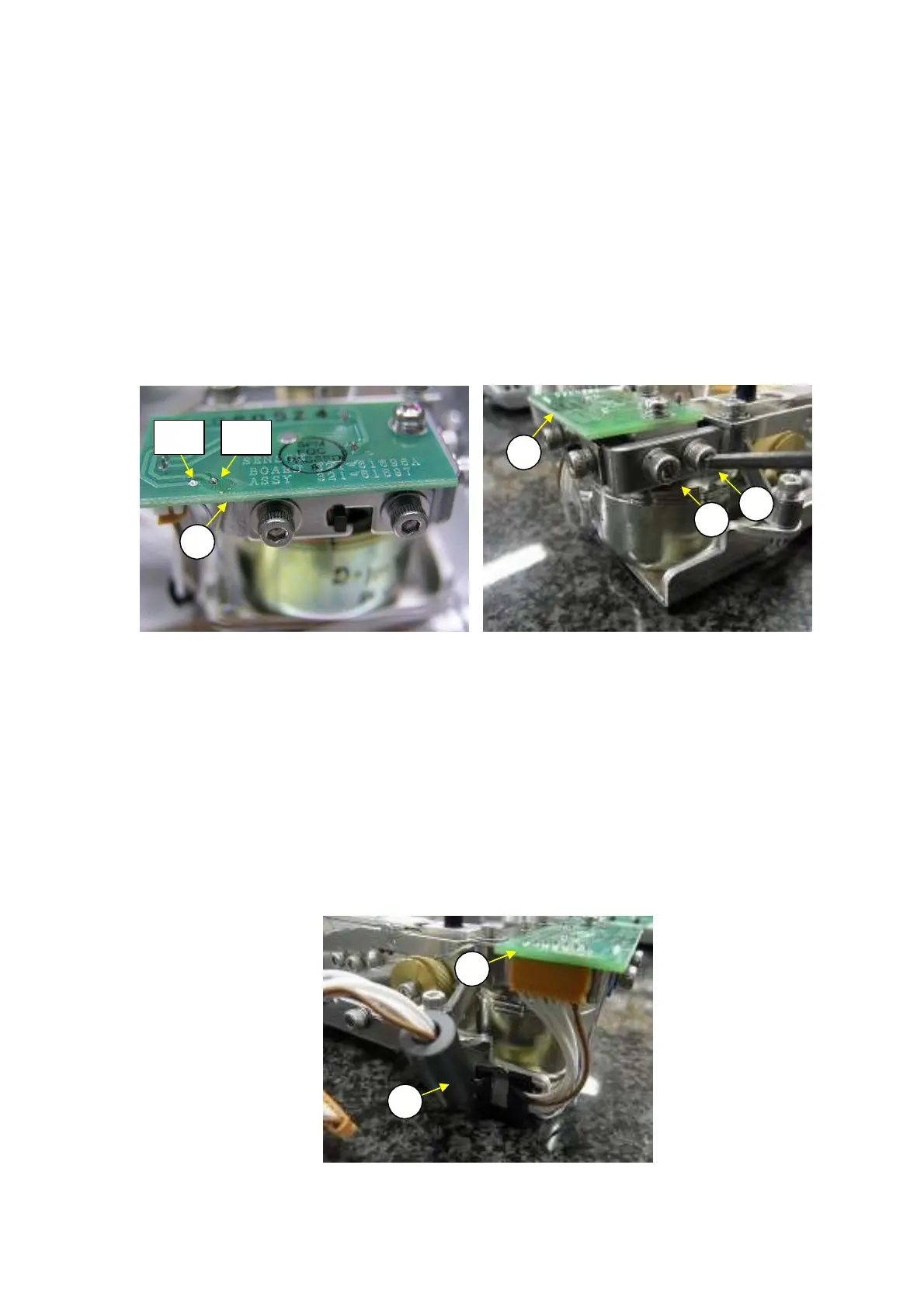
1) Remove the DBS unit assembly (1) using the same procedure as described in 2.3.6 Replacing the
DBS Unit Assembly (U1).
Unsolder the temperature sensor cables connected to the detector assembly (U11) (Fig. 25).
Note: Yellow wire is for TP1 and blue wire is for TP2
Disconnect connector J25 on the ILS 7S-7S-140 cable (U19), which is connected to the detector
assembly (U11).
Note: When disconnecting the connector, be careful not to contact the lever assembly (U7)
and damage the elastic support.
Loosen and remove the two P3 M3
×
10 socket head bolts (U53) that fasten the detector assembly
(U11) (Fig. 26).
2)
3)
4)
U11
U
3
U
3
U11
Fig. 25 Fig. 26
5)
6)
7)
Install the detector assembly (U11) by reversing steps 4 to 7 above.
Adjust the detector height according to 4.1.1 Adjusting the Detector Assembly (U11) Height.
Reassemble by reversing steps 1 to 4 above.
N
te: Secu
el
cl
mp the ILS
S-
S-1
0c
ble
U1
) in a slack st
te,
s sh
wn, to
e
ent
any pulling or upward pushing forces from acting on the detector assembly (U11)
(Fig. 27).
U11
U19
Fig. 27
TP1
TP2
DBS-SH-e-1210 23