2.3.1
e
l
cing the LS
Ca
le Assembl
C
)
1) Separate the case assembly (S2) and heater case assembly (C1) by following the procedure in
2.3.15 Replacing the Fan Cable Assembly (C5).
Remove the 2
×
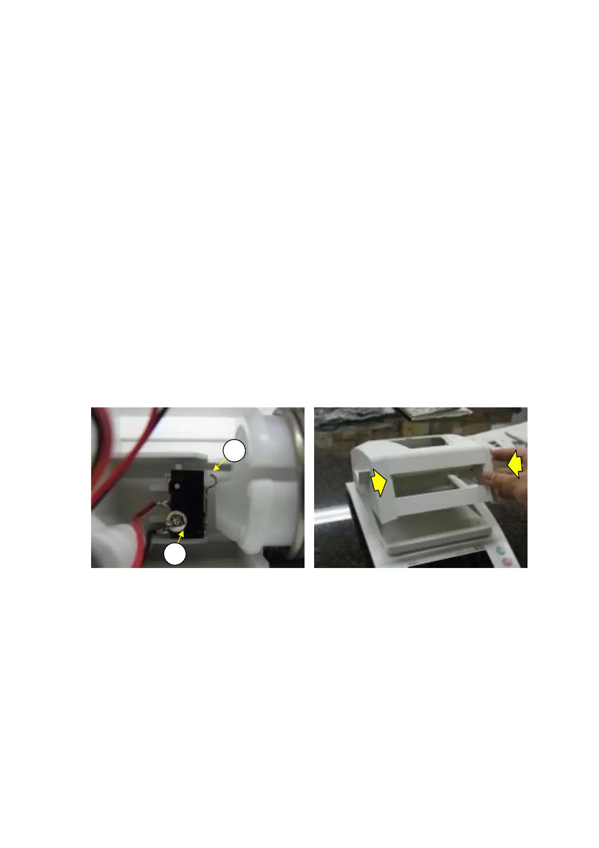
12 self-tapping screw (C51) and then the LSW cable assembly (C6).
Fasten the LSW cable assembly (C6) to the top base using the 2
×
12 self-tapping screw (C51)
(Fig.44).
Note: Confirm that the LSW is ON in this state.
2)
3)
4) Insert the wires from the fan cable assembly (C5) and LSW cable assembly (C6) into the slit in the
top base (C3) and hold them in place (Fig. 43).
5) Reassemble by reversing step 1 above.
Note: Make sure no wires are pinched between the case assembly (S2) and top base (C3).
6) When replacing the LSW cable assembly (C6), confirm that the LSW functions properly when it is
assembled with the case assembly (S2), by opening and closing the heater cover.
Note: Confirm the LSW functions properly in the following modes.
1. Close slowly.
⇒
If it does not function properly, retighten LSW screws or replace LSW.
2. Close while pressing laterally on heater cover (Fig. 45). ⇒ Move LSW closer to hinges and
retighten.
C6
1)
2)
C
1
Fig.44 Fig. 45
DBS-SH-e-1210 31