2.3.
e
l
cing the DBS Unit Assembl
U1)
1) Disassemble the balance down to the case assembly (S2) by following the procedure in 2.2
Removing the case
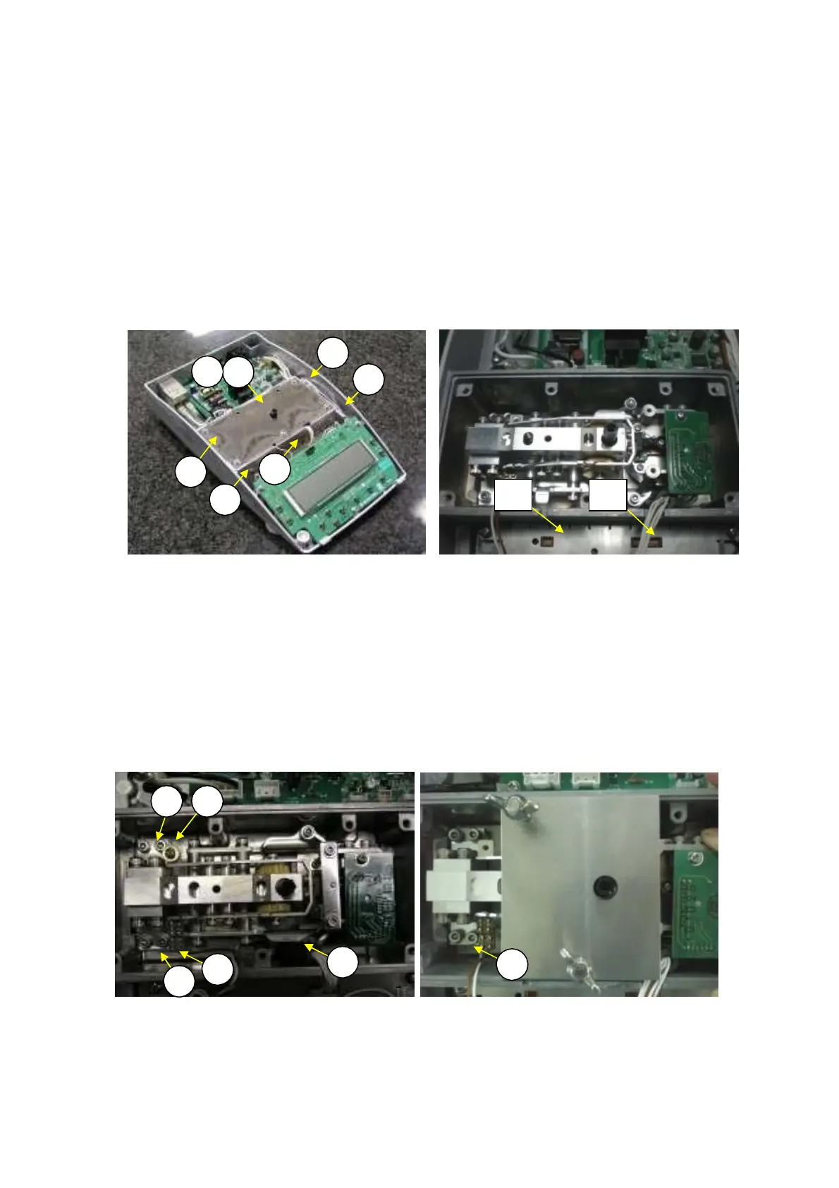
Loosen the five P4 M4
×
16 screws (62) and remove the upper unit cover (24) and lower unit cover
(23) (Fig. 21).
Note: There is no screw on 2 position of rear center in this status,since fasten with
case assembly(S2)
Insert the lever positioning pin (J1) into the lever fastener hole on the top of the OPF, up to the
reference line.
Disconnect the cables from connectors J2 and J3 on the analog board assembly (B3) (Fig. 22).
2)
3)
4)
2
23
24
2
2
2
2
Fig. 21 Fig. 22
5) Loosen and remove the four P4 M4
×
14 socket head bolts (61) that fasten the DBS unit assembly
(U1) (Fig. 23).
Note: When lifting the DBS unit assembly (U1), do not hold it by the parallel guides or
movable posts.
6) Install a new DBS unit assembly (U1) by using a unit assembly positioning jig (J8) to position the
assembly and reversing steps 2 to 5 above (Fig. 24).
Note: Be careful not to pinch wires when installing the unit cover.
1
1
U1
U1
1
1
Fig. 23 Fig. 24
7P 2P
DBS-SH-e-1210 21